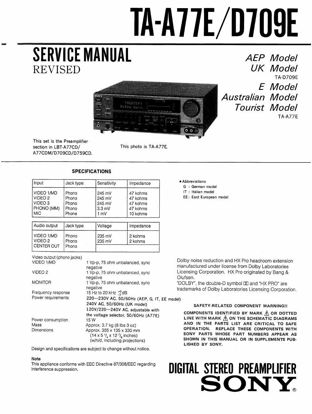
Sony ta a 77 e service manual

This is the 42 pages manual for sony ta a 77 e service manual.
Read or download the pdf for free. If you want to contribute, please mail your pdfs to info@audioservicemanuals.com.

Page: 1 / 42
left right
sony ta a 77 e service manual

Extracted text from sony ta a 77 e service manual (Ocr-read)


Page 1

This set is the Preamplifier
section in LBT~A77CD/

III-A'I'IE/D'IIIQE

SERVICE MANUAL

REVISED

This photo is TA-A77E.

AEP Model
UK Model

TA-D709E

E Model
Australian Model
Tourist Model

TA-A77 E

A77CDM/D709CD/D7590D.
SPECIFICATIONS
. . . 0 Abbreviations
Input Jack type Sensitivity Impedance G : German mode.
VIDEO i/MD Phono 245 mV 47 kohms T i "3 Wde'
VIDEO 2 Phono 245 mV 47 kohms EE= Ea Emma" mde'
VIDEO 3 Phono 245 mV 47 kohms
PHONO (MM) Phono 3.3 mV 47 kohms
MIC Phone 1 mV 10 kohms
Audio output Jack type Voltage Impedance
VIDEO 1/MD Phono 235 mV 2 kohms
VIDEO 2 Phono 235 mV 2 kohms
CENTER OUT Phono
VISTECOOIU/ttelg (phono jacks) 1 Vp-p 75 ohm unbalanced sync Dolby noise reduction and HX Pro headroom extension
negative ' manufactured under license from Dolby Laboratories
VIDEO 2 1 Vp-p' 75 ohm unbalanced, sync Licensing Corporation. HX Pro originated by Bang &
negative Olufsen.
MONITOR 1 Vp-p, 75 ohm unbalanced, sync 'DOLBY", the double~D symbol m and "HX PRO" are

Frequency response
Power requirements

Power consumption

Mass
Dimensions

negative

15 Hz to 20 kHz :ng3

trademarks of Dolby Laboratories Licensing Corporation

220-230V AC, 50/60Hz (AEP, G, IT, EE model)
240V AC, 50/60Hz (UK model)

120V/220-240V AC, adjustable with
the voltage selector, 50/60Hz (A77E)

15W

Approx. 3.7 kg (8 lbs 3 oz)

Approx. 355 x 135 x 330 mm
(14 x 5 l, x 12 7/8 inches)
(w/hld, including projections)

Design and specifications are subject to change without notice.

Note

This appliance conforms with EEC Directive 87/308/EEC regarding

interference suppression.

SA FETY-RELATED COMPONENT WARNINGII

COMPONENTS IDENTIFIED BY MARK A OR DOTTED
LINE WITH MARK A ON THE SCHEMATIC DIAGRAMS
AND IN THE PARTS LIST ARE CRITICAL TO SAFE
OPERATION. REPLACE THESE COMPONENTS WITH
SONY PARTS WHOSE PART NUMBERS APPEAR AS
SHOWN IN THIS MANUAL OR IN SUPPLEMENTS PUB-
LISHED BY SONY.

DIGITAL STEREO PREAMPLIFIER
S ON Y®

Page 2

MODEL IDENTIFICATION
-Specification Label-

AEP. UK, G, IT, EE model : TA-D709E
E, EA, AUS, JE, MY, SP model: TA-A77E

SONY MODEL N0. W/l/A

DIGITAL STEREO PREAMPLIFIER

WW

SERIAL N0.
MADE IN JAPAN

AEP, IT, EE model: AC: 220V-230V~50/60HZ 15W
UK model : AC: 240V~50/60Hz
G model : SYSTEM LBT-D709
AC: 220V-230V~50/60HZ 15W
AUS, E, JE,
MY, SP, EA model: AC: llOV-l20V/220V-240V~50/50HZ 15W

0 Abbreviations
G : German model
IT : Italian model
EE : East European model
EA : Saudi Arabia model
AUS: Australian model
JE : Tourist model
MY : Malaysia model
SP : Singapore model

TABLE OF CONTENTS


Section M flag
1. GENERAL
1-1. Location of Controls .............................. 3
2. SERVICE NOTES
2-1. Notes at Service and Inspection .................... 4
2-2. Removal of Joint .................................. 4
3. DIAGRAMS
3-1. Pin Description .................................... 5
3-2. Circuit Boards Location .................. 7
33. Semiconductor Lead Layouts . . .8
3-4, Block Diagram .................................. 12
3-5. Printed Wiring Boards

*Main Section (TYPE I)- ...................... 15
3-6. Schematic Diagram -Main Section (TYPE I); .,19
3-7. Schematic Diagram -Pane1 Section (TYPE I)- 24
3-8. Printed Wiring Boards

-Pane1 Section (TYPE I)- ...................... 29
3-9. Printed Wiring Boards

*Panel Section (TYPE I1) ..................... 31
3-10. Schematic Diagram -Pane1 Section (TYPE II)- 33

3-11.
3-12

3-13.
3-14i
3-15.
3-16.
3-17.
3-18,

3-19.
3-20.

4.
4~1.
4-2

5.

Schematic Diagram -Main Section (TYPE [1)7 ..38
Printed Wiring Boards

-Main Section (TYPE [he ...................... 43
Printed Wiring Boards
*Main Section (TYPE III)- ...................... 47

Schematic Diagram -Main Section (TYPE III)- 51
Schematic Diagram *Panel Section (TYPE III)# . .56
Printed Wiring Boards

~Pane1 Section (TYPE Hui ...................... 61
Printed Wiring Boards
#Panel Section (TYPE IV)- ...................... 63

Schematic Diagram *Panel Section (TYPE IV)7 , .65
Schematic Diagram -Main Section (TYPE IV)- . .70
Printed Wiring Boards

-Main Section (TYPE IV)~ ...................... 75

EXPLODED VIEWS

Front Panel Section ..,.79
Chassis Section ....... . .80
ELECTRICAL PARTS LIST ...................... 81