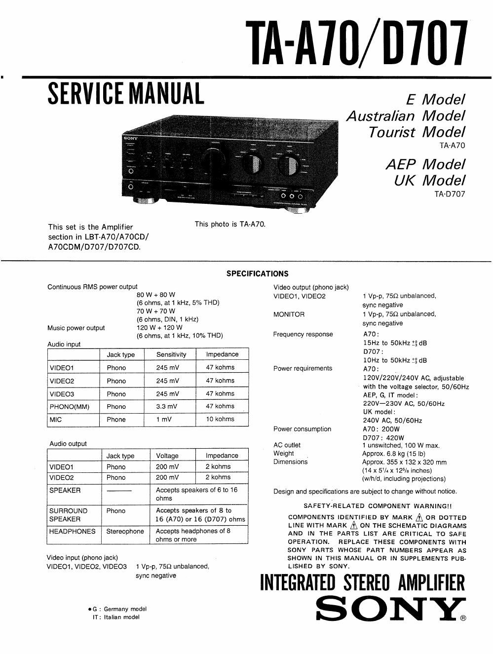
Sony ta a 70 service manual

This is the 22 pages manual for sony ta a 70 service manual.
Read or download the pdf for free. If you want to contribute, please mail your pdfs to info@audioservicemanuals.com.

Page: 1 / 22
left right
sony ta a 70 service manual

Extracted text from sony ta a 70 service manual (Ocr-read)


Page 1

TA-AIII/D'Ifl'l

SERVICE MANUAL

E Model
Australian Model
Tourist Model
TA-A7O

AEP Model

UK Model

TA-D707
This set is the Amplifier This Ph°t° 5 TAA7°~
section in LBT-A70/A7OCD/
A7OCDM/D707/D707CD.
SPECIFICATIONS
Continuous HMS power output Video output (phono iack)
80 W + 80 W VlDEOi, VIDE02 1 Vp-p, 750 unbalanced,
(6 ohms, at 1 kHz, 5% THD) sync negative
Zggrgsfim 1 kHz) MONITOR 1 Vp-p, 75:2 unbalanced,
Music power output 120 w + 120 w sync negat've
(6 ohms, at 1 kHz, 10% THD) Frequency response A70 :
Audio input 15Hz to 50kHz :3 dB
Jack e Sensitivit lm edance D707 1
typ y P IOHZ to 50kHz :3 dB
VlDEO1 Phone 245 mV 47 kohms Power requirements A70: .
VIDE02 Phone 245 mV 47 kohms 1?°V/22°V/24°V AC' adIUStab'e
With the voltage selector, 50/60Hz
VIDE03 Phone 245 mV 47 kohms AEP, G, lT model:
PHONO(MM) Phono 3.3 mV 47 kohms (W-23°" ACI 50/60HZ
UK model:
MIC Phone 1 mV 10 kohms 240V AC, 50/60Hz
Power consumption A70: 200W
. D707: 420w
AudIo output AC outlet 1 unswitched, 100 W max,
Jack type Voltage Impedance \élleight _ 2pprox. 2%,sz g: 'b)
ImenSIons rox. x 1 x 32
VIDEO1 Phone 200 mV 2 kohms (131px 5% x 12% inches? mm
VIDE02 Phone 200 mV 2 kohms (w/h/d, including projections)
SPEAKER Accepts speakers 0f 6 to 15 Design and specifications are subject to change without notice.
ohms .
F Y-
SURROUND Phono Accepts speakers of 8 to SA ET RELATED COMPONENT WARNINGH
SPEAKER 16 (A70) or 16 (D707) ohms COMPONENTS IDENTIFIED BY MARK A on DOTTED
LINE WITH MARK A93 ON THE SCHEMATIC DIAGRAMS
HEADPHONES Stereophone Accepts headphones of 8 AND IN THE pARTs LIST ARE CRITICAL To 5A5;
Ohms 0' m°re OPERATION. REPLACE THESE COMPONENTS WITH

Video input (phono iack)

VIDEO1, VIDEOZ, VIDEOS

06 : Germany model

1 Vp-p, 759 unbalanced,

sync negative

IT: Italian model

SONY PARTS WHOSE PART NUMBERS APPEAR AS
SHOWN IN THIS MANUAL OR IN SUPPLEMENTS PUB-
LISHED BY SONY.

III :GRATED STEREIJ AMPLIFIER
S ONY;

Page 2

TA-A70/ D707

MODEL IDENTIFICATION
-Specification Label-

TABLE OF CONTENTS

Section Title Page
E, TR, EA, AUS model: TA-A7O
AEP, UK, G, IT model: TA~D707
1. GENERAL
1-1. Location of Controls .............................. 2
SONY MODEL Norm
INTEGRATED STEREO AMPLIFIER 2- SERVICE NOTES
Wm 2-ll Removal of Fan Case .............................. 3
2-2. Removal of Joint .................................. 3
SERIAL No. 3. DISASSEMBLY
MADE IN JAPAN 3-1 Case ............................................ 4
3-2. Front Panel Assy .................................. 4
3-3. Panel Board ...................................... 4
AEP, IT modeI : AC: 220V-230V~50/60Hz 3.4. Back Panel, Fan Case Assy ....................... 5
UK model : AC: 240V~50/60Hz 3 5 J . t
G model I SYSTEM LBT-D707 - . orn .............................................. 5
AC: 220V-230V~50/60Hz 3»6. Mam Board ...................................... 5
E, TR, EA, AUS model: AC: 120V/220V/240V~50/60Hz 200W
ITR : Tourist model 4' DIAGRAMS
EA : Saudi Arabia model 4-1. Block Dlagram .................................... 6
AUS: Australian model 4-2, Circuit Boards Location .......................... 9
fr IGermany model 4-3, Printed Wiring Boards ............................ 10
tal'an "mm 44. Schematic Diagram ....................... 15
4-5. Semiconductor Lead Layouts ...................... 20
4-6. Pins Description of IC701 (PD75106CW-195) rrrrrr 24
5. EXPLODED VIEWS
5-1, Cabinet Section .................................. 26
5-2. Chassis Section ................................. 27
6. ELECTRICAL PARTS LIST ...................... 28
SECTION 1
G EN ERAL

1-1. LOCATION OF CONTROLS

|
N
l

EIEEEIHIEHEIE

EQEEEEE

This section is extracted from
instruction manual.

POWER switch (8)
BASS control (9)
TREBLE control (9)
BALANCE control (9)
VOLUME control and indicator (9)
VIDEO FUNCTION selector and indicator (66)
AUDIO FUNCTION selector and indicator (33, 66)
VIDEO 3 INPUT jacks (7)
PROGRAM FUNCTION buttons (65)
Numeric buttons (1 - 3) and indicators

SET button
BASS SYNTHESIZER LEVEL control (9)
BASS SYNTHE(sizer) button and indicator (9)
MIC (microphone) LEVEL control (33)
MIC (microphone) jack (38)
HEADPHONES jack (9)
E0 REC button and indicator (22)
CD DIRECT button and indicator (9)