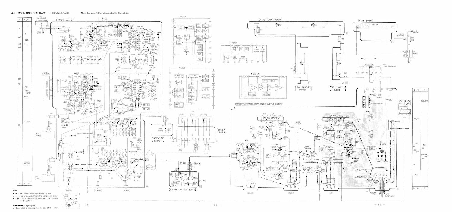
Sony str v 1 schematics

This is the 4 pages manual for sony str v 1 schematics.
Read or download the pdf for free. If you want to contribute, please mail your pdfs to info@audioservicemanuals.com.

Page: 1 / 4
left right
sony str v 1 schematics

Extracted text from sony str v 1 schematics (Ocr-read)


Page 2

FM SECTION

STR-Vl

Discriminator Adjustment

0 Secondary-Side Adjustment distort/On
meter
setup I [I
fm
signa/ I I set I I
generator
: 1 CK /: I I I

\\
FM ANT REC OUT
FM Signal Generator Setting:
Currier frequency: 98 M117.
Output level: lmV (60 dB)
Modulation: 400112, 75 kllr deviation
(100%)
Procedure:
1, Tune the set to 98 M117.

2. Adjust the secondary-side coretbluc) of 1171202
for a minimum reading on the distortion meter.

0 Primary-side Adjustment

Procedure:
1 DLtunc the set.

3. Adjust the primary-Side core (white) of 1131201

for the center posrtion on the TUNING meter.

TUNING

Note: Repeat the secondary-side and primary-
side adjustments several times.

lF T201
primary-Side
(Vt/h: tel

IF T202
secondary-side
(blue)

VCO Adjustment
A) With Frequency Counter

fm I I
s/gna/ set
generator I I \

J I \

\\
FM ANT

Setup:

FM Signal Generator Setting:

Carrier frequency: 98 Mllz
Modulation: no modulation
Output level: 1 mV (60 dB)

Procedure:
1. Tune the set to 98 M112,

2. Adjust RTZOI for l9kHzi1001-l7 on the
counter.

B) Without Frequency Counter

Procedure:
1. Tune the set to FM stereo Signals.

2. Turn RTZOI clockwise or counterclockwise and
secure RTZOI at thc center in lighting-up range
of stereo lamp as shown below.

7 76
frequency counter ICZOZ
8 9
external
preamplifier R230
to ground
center ll7 lighting up range
l/gh ting up range
l t I
\ \
\ \-/ /
\ /
\ \ RT207

STR-Vl

FM IF Alignment

Setup:
FUNCTION selector, FM VTVM
fm set /
signal 0-0 FM 0-0
generator I I ANT / I I
C I t 3 C I l :

REC OUT

FM Signal Generator Setting:

Currier frequency: 98 M117.

Modulation: 400117,, 75 kHz devuttion
(100%)
Output level: 4.5;1V (l3dB)

Pro eedure:

'lune the set to 98M11z and adjust 11-T1 tor
maximum reading on the VTVM.

"w Him-TH ' 0'

0 Replacement Semiconductors

SECTION 4
DIAGRAMS

For replacement. use semiconductors except int 1.

01-4: ZSC710

» ,c
5,.IIEI
5
a'
c r

(ZSC134ZB, 28013420
5
@ \r
5' c 5

0401, 402
0701, 702
0751, 752
0802

0501, 502)
0551 , 552

,c
61
5
Fee

(ZSCBOOF)

c
.g
5
F5},

I: 2861 364 (280945Pl

2301362 (ZSC9OOF1

0801: ZSC1096 (ZSC1096K)

H3201: uPC1167C
|C202: MPC1161C
10401: MPC11780

[615141.112111113

t 7 a 4 s t: 7 u
(Tupi/row!

IC701,751: HA1370

C

.2 1455159!)
lekmvxtttt' mw/

01,401 ,
0803411) . 1szo7eA (1320761
0201: R03.9E (RD3.9)
D402: RD6,8EB tRDGB)
D803-306: 1052 (10m)
0307: RD27

"no.

A

D202: SLP141D
M

D801 : S3VC40

W/ mm

A
1
2 3
1 2 a
W-o-Kd

made more

(10DC1N)

D802: S3VC40R

,/ blown

2 3
2 3
H¢1>-H:
(1 DDC1 R )
I950
cathcdz~ .7 [3mm

Lem

STR-Vl