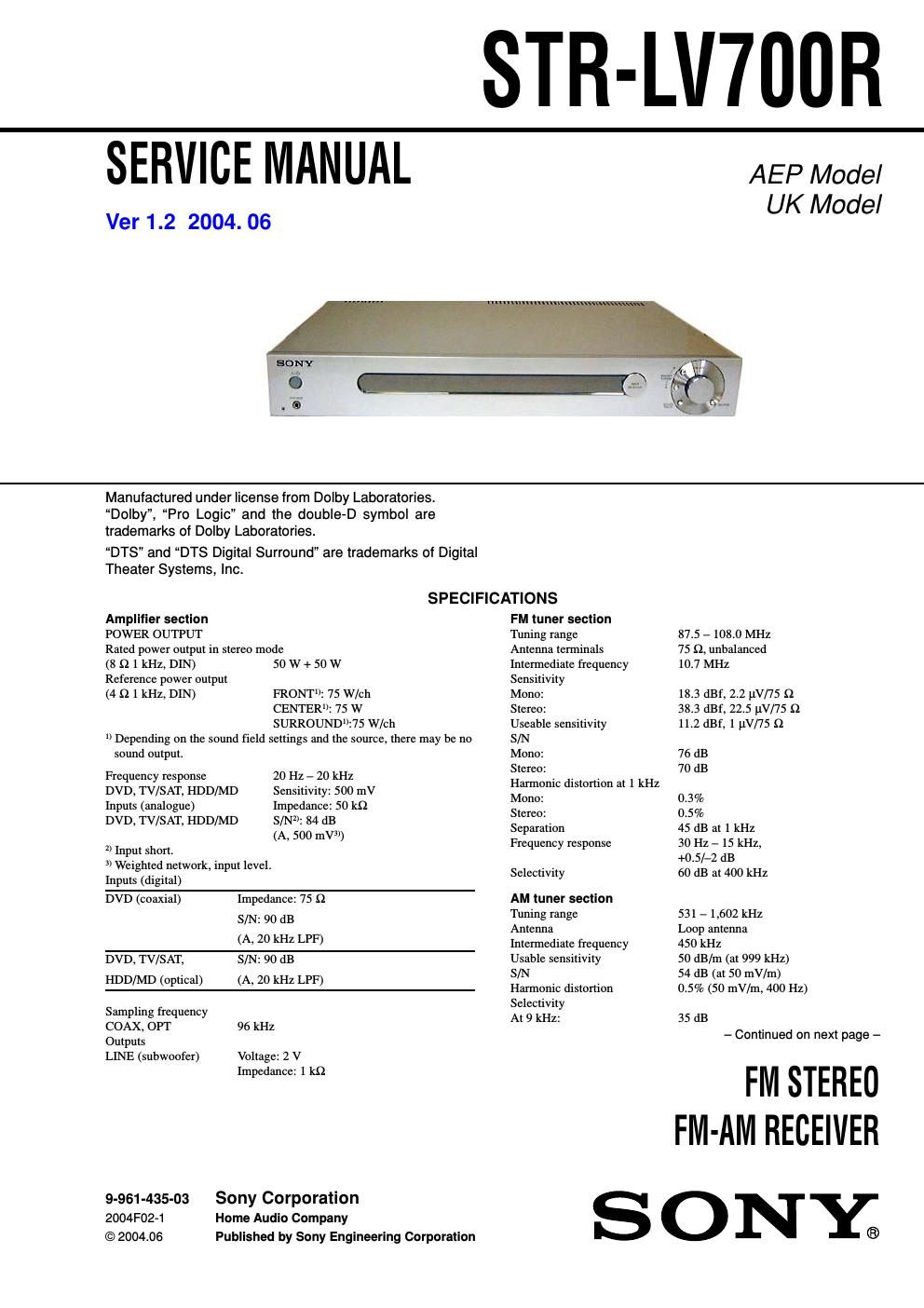
Sony str lv 700 r service manual

This is the 46 pages manual for sony str lv 700 r service manual.
Read or download the pdf for free. If you want to contribute, please mail your pdfs to info@audioservicemanuals.com.

Page: 1 / 46
left right
sony str lv 700 r service manual

Extracted text from sony str lv 700 r service manual (Ocr-read)


Page 1

STR-LV700R 2 Unleaded solder Boards requiring use of unleaded solder are printed with the lead- free mark (LF) indicating the solder contains no lead. (Caution: Some printed circuit boards may not come printed with the lead free mark due to their particular size.) : LEAD FREE MARK Unleaded solder has the following characteristics. - Unleaded solder melts at a temperature about 40 Β°C higher than ordinary solder. Ordinary soldering irons can be used but the iron tip has to be applied to the solder joint for a slightly longer time. Soldering irons using a temperature regulator should be set to about 350 Β°C. Caution: The printed pattern (copper foil) may peel away if the heated tip is applied for too long, so be careful! T ABLE OF CONTENTS SAFETY-RELATED COMPONENT WARNING!! COMPONENTS IDENTIFIED BY MARK 0 OR DOTTED LINE WITH MARK 0 ON THE SCHEMATIC DIAGRAMS AND IN THE PA RTS LIST ARE CRITICAL TO SAFE OPERATION. REPLACE THESE COMPONENTS WITH SONY PARTS WHOSE PART NUM- BERS APPEAR AS SHOWN IN THIS MANUAL OR IN SUPPLE- MENTS PUBLISHED BY SONY. Specifications ........................................................................\ .... 1 1.GENERAL ...................................................................... 3 2. SERVICING NOTES ................................................... 4 3. TEST MODE ................................................................. 7 4. DIAGRAMS 4-1. IC Pin Function Descriptions ................................ 13 4-2. Block Diagrams -“ T uner/DSP Section -“............... 18 Block Diagrams -“ Display/Power Section -“......... 19 4-3. Printed Wiring Boards -“ Digital Section (Side A)-“................................... 20 Printed Wiring Boards -“ Digital Section (Side B)-“................................... 21 4-4. Schematic Diagram -“ Digital Section (1/3)-“........ 22 4-5. Schematic Diagram -“ Digital Section (2/3)-“........ 23 4-6. Schematic Diagram -“ Digital Section (3/3)-“........ 24 4-7. Schematic Diagram -“ Amp Section (1/2)-“........... 25 4-8. Schematic Diagram -“ Amp Section (2/2)-“........... 26 4-9. Printed Wiring Boards -“ Amp Section-“................ 27 4-10. Schematic Diagram -“ Display Section-“............... 28 4-11. Printed Wiring Boards -“ Display Section-“........... 29 4-12. Schematic Diagram -“ Power Section-“.................. 30 4-13. Printed Wiring Boards-“ Power Section-“.............. 31 4-14. IC Block Diagrams................................................ 32 5. EXPLODED VIEWS 5-1. Front Panel Section................................................. 33 5-2. Cabinet Section ........................................................ 34 6. ELECTRICAL PARTS LIST .................................... 35 Video section Input VIDEO: 1 Vp-p 75 -„¦ Output MONITOR: 1 Vp-p 75 -„¦ Network Media section Hardware decoder MPEG2 Maximum 8 Mbps, 720 x 480 pixels, 30 fps MPEG1 1.41 Mbps, 352 x 240 pixels, 30 fps Playable file formats Giga Pocket video MPEG2, MPEG1 SonicStage music ATRAC3, ATRAC3plus,WAV, MP3. WMA is not supported. Photo Server images BMP, TIFF, GIF, JPEG,PNG Interface Network 100Base-TX Compatible computers VAIO computers bought after October 2003, running Windows XP Professional or Windows XP Home Edition General Power requirements 230 V AC, 50/60 Hz Power consumption 95 W Dimensions 430 x 65 x 288 mm including projections and controls Mass (approx.) 3.2 kg Pa ckag e contents AM loop antenna (1) Allen screwdriver (1) Connection adapter (1) Cross-wired cable (1) FM wire antenna (1) Network cable (approx. 170 cm, 1) Network cable ferrite core (1) R6 (AA) batteries (2) Remote control (RM-U70R)(1) Speaker cable ferrite core (2) Speaker plug (5) Design and specifications are subject to change without notice. - Strong viscosity Unleaded solder is more viscous (sticky, less prone to flow) than ordinary solder so use caution not to let solder bridges occur such as on IC pins, etc. - Usable with ordinary solder It is best to use only unleaded solder but unleaded solder may also be added to ordinary solder. Notes on chip component replacement - Never reuse a disconnected chip component. - Notice that the minus side of a tantalum capacitor may be dam- aged by heat. V er 1.1

Page 2

STR-LV700R 3 SECTION 1GENERAL This section is extracted from instruction manual. Main unit Display 2 IN PU T SELECTOR 3 MU TING 6 P HONES jack 8 PR ESET TUNING +/-“ 4 S OUND FIELD 7 VOLUME 5 ?/1 (power) 1 Alphabetical order Symbols 1 2 35 4 6 7 8