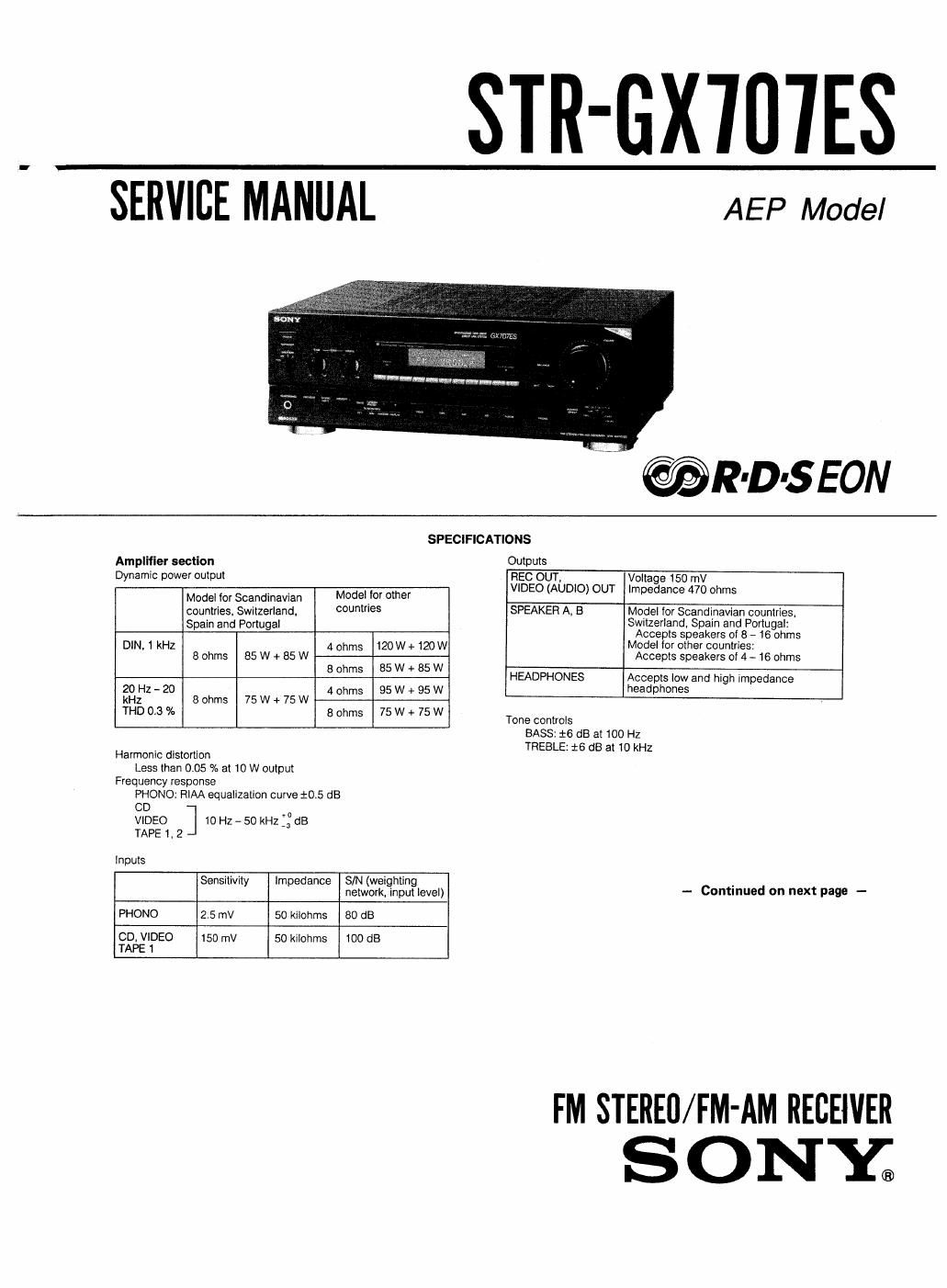
Sony str gx 707 es service manual

This is the 27 pages manual for sony str gx 707 es service manual.
Read or download the pdf for free. If you want to contribute, please mail your pdfs to info@audioservicemanuals.com.

Page: 1 / 27
left right
sony str gx 707 es service manual

Extracted text from sony str gx 707 es service manual (Ocr-read)


Page 1

jSIR-GX'IUIES

"SERVICE MANUAL

AEP Model

@R-D-SEON

Amplifier section
Dynamic power output

SPECIFICATIONS

Modei for Scandinavian Modeivfor 0919'
countries. Switzerlandv countries
Spain and Portugal
DiN.1kHZ 4ohms 120W+120W
8ohms 85W+85W
Bohms 85W+85W
ZOHZ-ZU thms 95W+95W
kHz 8 ohms 75 W + 75 W
THD 0.3 % 8 ohms 75 W + 75 W
Harmonic distortion
Less than 0.05 % at 10 W output
Frequency response
PHONO: RIAA equalization curve $0.5 dB
CD -
VIDEO 10 Hz - 50 kHz ff dB
TAPE I. 2 -
Inputs
Sensitivity Impedance S/N (weighting
network. input level)
PHONO 2.5 UN 50 kilohms 80 dB
CD, VIDEO 150 mV 50 kiiohms 00 dB
TAPE 1

Outputs

REC OUT, Voitage 150 mV
VIDEO (AUDIO) OUT Impedance 470 ohms

SPEAKER A. B Mode! for Scandinavian countries.
Switzerland Spain and Portugal:
Accepts speakers of 8 ~ 16 ohms
Model for other countries:
Accepts speakers of 4 ~ 16 ohms

HEADPHONES Accepts Iow and high impedance
head phones

Tone controls
BASS: 16 dB at 100 Hz
TREBLE: i6 (18 at 10 kHz

- Continued on next page -

FM STEREO/FM-AM RECEIVER
S O NYE

Page 2

Tuner section

TABLE OF CONTENTS


FM tuner section AM tuner section .
. Section lute Bane
Tunlng range 87.5- 108 MHZ 531 - 1.602 kHz
E Tl N 1. GENERAL
Antenna 75 ohms. unbalanced External antenna S C ,0
terminals terminal Identifying the Paris and Controls N3
SensiW 3} is can 22 )1V (mono) SECTION 2. ELECTRICAL ADJUSTMENTS ................... 5
45 13 quietlng 40 (BI. 245 W (stereo) --
Usable. 11,2 dBl. 1 "V (IHF) Loop antenna: SECTION 3. IC PIN FUNCTIONS .................................... 6
sensmwty 300 try (at 999 kHz)
Signal to noise 7!) d8( ) B( / ) SECTION 4. DIAGRAMS
' ' mono 54d atSOme , . .
ratio 56 dB (stereo) 4-1. Circuit Boards Location . 8
4-2. Block Diagram 9
Harmqnic 0.3% (mono), 0.5% 0.57° (at 50 mV/m, 4.3. Printed Wiring Board - Main Section -
dlstortlon (stereo) 3 I kHz 400 HZ) 4-4, Schematic Diagram -- Main Section -.
Selectivity 50 dB at 400 kHz 30 dB at 9 kHz 4-5 Printed Wiring Board - Display Section - 20
, 4-6r Schematic Diagram - Display Section 23
Separation 45 dB at 1 kHz - 4-7. Semiconductor Lead Layouts 26
Frequency 30 Hz _15 kHz .: dB _ 4-8. IC Block Diagrams
response '
SECTION 5. EXPLODED VIEWS
General 5-1. From Panel Section
System S~2. Chassis Section
Tuner section: PLL quartz-locked digital synthesizer system
Preamplifier 590: IowWise NF YPe equalile' an) SECTION 6. ELECTRICAL PARTS LIST ....................... 31
Power amplifier section: pure complementary SEPP
Power requirements
220 - 230 V AC. 50/60 HZ
Power consumption
Model for Scandinavian countries, Switzerland. Spain and
Portugal: 145 W
Model for other countries: 220 W
AC outlet
WWW WWW MODELIDENTIFICATION
Dimensions _
Approx. 430 x 150 x 375 mm (w/h/d) _ BACK PANEL -

(17 x 5 7/4 x 14 3/, inches)
including projecting parts and controls

M855

spams

Approx. 9.5 kg (21 lb 1 oz)
Accessories supplied
FM wire antenna (1) (Except German model)
AM loop antenna (1)
Remote Commander RM-S103 (1)
Sony batteries SUM-3(NS) (2)

Design and specifications are subject to change without notice,

Note
This appliance conforms with EEC Directive 87/308/EEC regarding
Interference suppression.

co co _
Boo @@

4-958-154-113 AE2 (AEPE) : Scandinavian countries. Switzerland.
Spain and Portugal

4-958-154-0EI AEt (AEPi) :Other European countries

4»958-154-2E\ G : Germany

SAFETY-RELATED COMPONENT WARNINGII

COMPONENTS IDENTIFIED BY MARK A OR DOTTED
LINE WITH MARK A ON THE SCHEMATIC DIAGRAMS
AND IN THE PARTS LIST ARE CRITICAL TO SAFE
OPERATION. REPLACE THESE COMPONENTS WITH
SONY PARTS WHOSE PART NUMBERS APPEAR AS
SHOWN IN THIS MANUAL OR IN SUPPLEMENTS PUB-
LISHED BV SONY.

i2-