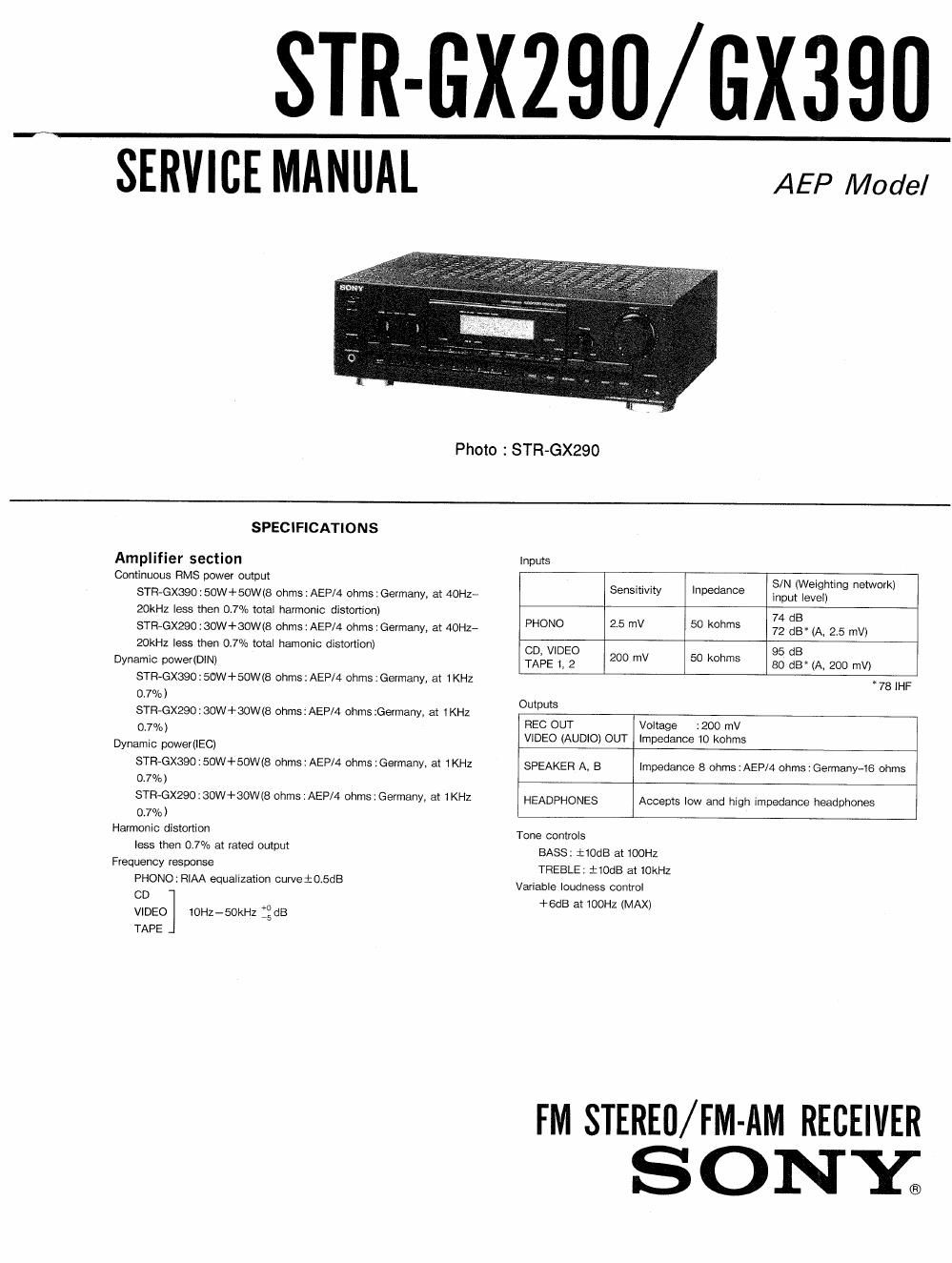
Sony str gx 290 service manual

This is the 28 pages manual for sony str gx 290 service manual.
Read or download the pdf for free. If you want to contribute, please mail your pdfs to info@audioservicemanuals.com.

Page: 1 / 28
left right
sony str gx 290 service manual

Extracted text from sony str gx 290 service manual (Ocr-read)


Page 2

Tuner section

STR-GX290/GX390

FM tuner section

AM tuner section

Tuning range

875-108 MHZ

531-1602 kHz

11,2 dBf, 1 WIHF):
Germany

Antenna External antenna
terminals 75 ohms, unbalanced terminal
Sensitivity at 183 dBf, 4.5 uV(mo-
46 dB : AEP/50 dB: no):AEP
GeiTiany 13.3 dBf, 225 yV(mo-
qule mg no): Germany

88.3 dBf, 45 uV(ster-

eo):AEP

3&3 dBf, 22,5 )AVISI-

ereo) : Germany
Usable 11,2dBf , 2 uV(lHF): Loop antenna:
sensitivity AEP 500 ,Ntat 1000 kHz)

Signal-to-noise

76 dB(mono) :AEP

54 dB(at 50 mV/m)

ratio 70 dB(mono):Germa-
Y
70 dB (stereo):AEP
66 dB (stereo) : Germ-
any
Harmonic 0.3%(mono) 0.5%(at 5O mV/m, 400 Hz
distortion 0r5%(stereo) at 1kHz )
Selectivity 60 dB at 400 kHz 40 dB at 10 kHztAEP
30 dB at 9 kszGermany
Separation 45 dB at 1 kHz
Frequency 30 Hz-15 kHzi;5 dB
response
Ge n e ra |
System

Tuner sectionzPLL quartz-locked digital synthesizer system
Preamplifier section: low-noise NF type equalizer amp
Power amplifier section:pure complementary SEPP

Power requirements

TABLE OF CONTENTS


Section Time Page

SECTION 1_ GENERAL ................. m... .................. mm. 3

SECTION 2. lo pm FUNCTION ........ ............. 4

SECTION 3. ELECTRICAL ADJUSTMENTS ~~~~~~~~~~~~~~~ 6
SECTION 4. DIAGRAMS

4.1 Circuit Boards Imtion ..... ........................ m... ....... 8

4.2, Semiconductor Lead Layouts ....... ................... . 9

4-3. Primed Wiring Bosrds -Main Section- ----------------- 11

4-4 Schematic Diagrams -Main Section- ~~~~~~~~~~~~~~~~~~~~ 15

IC Block Diagram ........ .................... 13

4-5. Printed Wiring Bosrds -Display Section- 19

4-6 Schematic Diagam -Display Section- 23

1C Block Diagrams 25

4-7i Schematic Diagram --Tuner Section- 26

IC Block Diagrams - r- 28

SECTION 5. EXPLODED VIEWS

5.1 Front Panel Section .......... ................. 29
5.2. Chassis semiannu... ................... ...................... . 30
SECTION 6. ELECTRICAL PARTS LIST ~~~~~ 31

220-230 V, 50/60 Hz
Power consumption
100 W (STFl-GXGQO)
Dimentions
430 X135 X 300 mm (w/h/d)
Weight
STR-GX39016r5 kg
STR-GX29026.0 kg
Accessories supplied
FM wire antenna (1):AEP model only
AM loop antenna (1)
Remote commander {STR-GX390 only)
RM-8103 (1)
Sony batteries SUM-3 (NS) (2)

SAFETY-RELATED COMPONENT WARNING! |

COMPONENTS IDENTIFIED BY MARK A OR DOTTED
LINE WITH MARK A ON THE SCHEMATIC DIAGRAMS
AND IN THE PARTS LIST ARE CRITICAL T0 SAFE
OPERATION. REPLACE THESE COMPONENTS WITH
SONY PARTS WHOSE PART NUMBERS APPEAR AS
SHOWN IN THIS MANUAL OR IN SUPPLEMENTS PUB-
LISHED BY SONY.