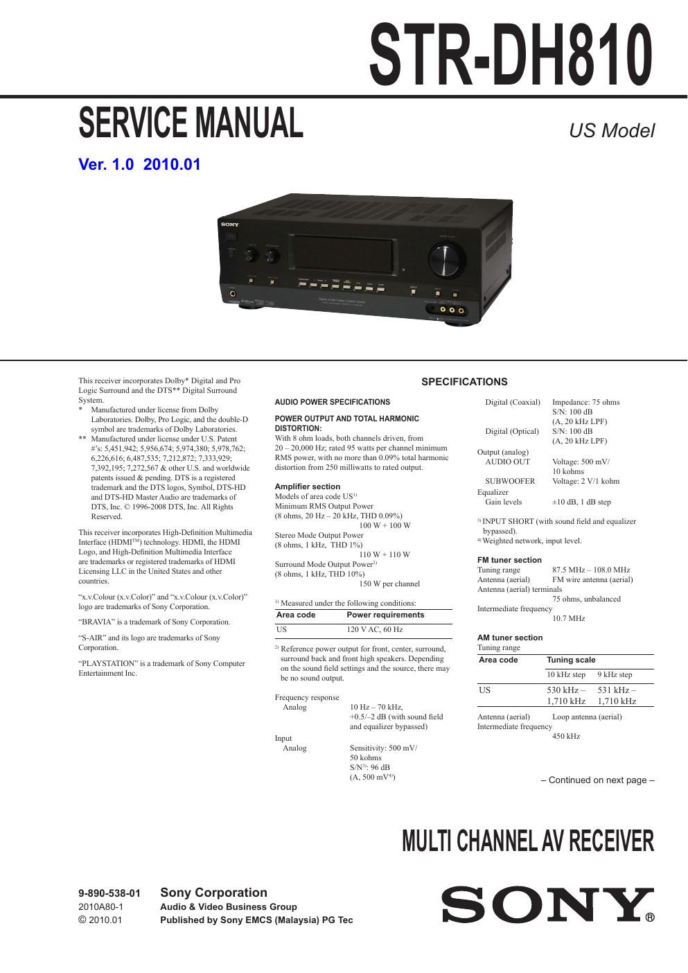
Sony str dh 810 ver 1 0 2010 01 service manual

This is the 84 pages manual for sony str dh 810 ver 1 0 2010 01 service manual.
Read or download the pdf for free. If you want to contribute, please mail your pdfs to info@audioservicemanuals.com.

Page: 1 / 84
left right
sony str dh 810 ver 1 0 2010 01 service manual

Extracted text from sony str dh 810 ver 1 0 2010 01 service manual (Ocr-read)


Page 1

STR-DH810

SERVICE MANUAL

Ver. 1.0 2010.01

US Model

Tlns recelver lncorporales Dolby* Dlgllal and Pm
Loglc Surround and me DTS Dlgllal Surround
System.
* Manufactured under license from Dolby
Laboratories, Dolby. Pro Logic. and the doubleeD
symbol are trademarks of Dolby Laboramnes.

** Manufactured under license under U S Palenl
e's: 5.451.942; 5,956.67 ;5,974.380 978,762;
6,226,616 6.487.53 2118727333929-
7.392.l9 7.272.567 & other us, and wol'ldwlde
palellls lssued & pending. DTS ls a l'engIered
lrademark and llle DTS logos. Symbol. DTSVHD
and DTSel-ID MnsterAudto are trademarks of
DTS, Inc. 1: 19961008 DTS. lne. All Rights
Reserved.

Tlus recelver incorporates ngerefinmon Vllllllllledla
lntertaee (l-lDMlN) teelrnology. HDMl, tlre HDMI
Logo. and Htgerefinurou MuIIlmedla Interface

are lrademarkS or reglslered trademarks of HDMI
Lloenslng LLC In tlae lJnrted Stares and other
Coumnes,

x.\l.Colour lx.y.Colorl" and x V.Cololll' (x.V.Color)"
logo are trademarks or Sony Corporation,

BRAVIA IS a Iradelnnrk ofSony Corporalloll.

"SeAIR" and us logo are trademarks ofSony
Comomnon.

PLAYSTATION" iS a trademark of Sony Computer
Eulenalumeul Inc,

9-890-538-01 Sony Corporation
2010A80-1 Audio & Video Business Group
© 2010.01

Published by Sony EMCS (Malaysia) PG Tec

SPECIFICATIONS

AUDIO POWER SPECIFICATIONS

POWER OUTPUT AND TOTAL HARMONIC
DISTORTION:

Wflh 8 ohm loads, bolil channels drlvell. from

20 , 20,000 Hz; raled 95 walls per channel lnlnilnunl
RMS power. wllh no more than 0.09% Imal harmonic
dismnlon from 250 mllllwalts lo ruled output.

Amplifier secion
ModeIs ofarea code US
Mlnlmunl RMS Oulpul Power
(8 ohms. 20 Hz 7 20 kHz. THD 0.09%)
I00 W 7 [00 W
Stereo Mode Ompm Power
(8 ohms. l kHz. Tl-lD |%)
I 10 W + I 10 W
Surround Mode Olllpul PowerEl
(8 ohms. I kHz. THD [0%)
I50 W per channel

" Measured under the followlllg condmons:

Area code Power requlrements

US IZOVAC,60HZ

3' Reference power outpm for front. ceuler. surround.
surround back and front lugll speakers. Dependlng
on Khe sound field setungs and the source. there may
be no sound output.

Frequency response
Annlog IO Hz , 70 kHz.
+0.52: dB (wulr sound field
and equallzer bypassed)

Input
Analog Sensruvuy: 500 luv
50 kolrms
SN": 96 dB
(A, 500 mV)

Drgual (Coaxlal) Impedance: 75 olnns
S/N: loo dB

(A, 10 kHz LPF)
S/N: loo dB

(A, 10 kHz LlF)

Dlgllal(0puca1)

Oulpm (analog!

AUDIO our Vollage: 500 my,
lo kohlns
SUBWOOFER Voltage. 2 v l kollm
qulallzer
Galn levels e10 dB, 1 dB step

;, INPUT SHORT (wllh sound field and equalizer
bypassed).
Welghled nemork. rnpur level,

FM tuner seciion
Tunlllg range 87.5 MHz , |08,0 Ml-lz
Alllellna (aerial) FM wlre amenna (ael'lal)
Antenna Iaerlal) terminals

75 ohms, unbalanced
Intermediate frequency

107 MHZ

AM tuner section
TIInlllg range

Area code Tuning scale
10 kHz step 9 kHz srep
US 530 kl-IZe 53lkl-127
1,710kl-lz 1,710kHz

Antenna Iaenall
Imermedlale frequency
450 kHz

Loop antenna (aerial)

- Continued on next page -

MULTI CHANNEL AV RECEIVER

SONY;

Page 2

STR-DH810

Video section
Inputs/ Outputs
Video: I Vprp, 75 ohms
COMPONENT VIDEO:
v: 1 Vprp. 75 ohms
131an 0.7 Vpep, 75 ohms
PK Ca. 0.7 Vpep, 75 ohms
80 MHZ HD Pass Through

Dlmensions (width/helght/depth) (Approx.)
430 mm X 157.5 mm ><
322mm(l7 In >< 6 1/4 in X
12 3/4 to) including projecting
parts and controls

Mass (Approx)

Models ofar'ea code US

7.9 kg (17 1b 7 oz)

- Remote commander RMVAAI049 (I)

- R6 (sizerAA) barterles (2)

- Optnmzer mlcmphone (ECMeAcz) ( 1)

General Supplied accessories
Power requirements - Operating Instructions
Area code Power requirements ' Quick Semi) Gude

- FM wne antenna (aenai) (1 )
US 120VAC,60 Hz

55%

- AM loop antenna (aerial) (1)

,

Power output (DIGITAL MEDIA PORT)
DC OUT: 5V, 0.7AMAX

Power consumption
Area code Power consumption

US 240 W

About area codes

The area code of the receiver you purchased is
shown on the lower right portion of the rear panel
(see the illustration below).

4-XXX-XXX-XXlX) AA

Area code

Any differences in operation, according to the area
code, are clearly indicated in the text, for example,
Models of area code AA only".

SAFETY-RELATED COMPONENT WARNING!

COMPONENTS IDENTIFIED BY MARK A OR DOTTED LINE
WITH MARK A ON THE SCHEMATIC DIAGRAMS AND IN
THE PARTS LIST ARE CRITICAL TO SAFE OPERATION.
REPLACE THESE COMPONENTS WITH SONY PARTS
WHOSE PART NUMBERS APPEAR AS SHOWN IN THIS
MANUAL OR IN SUPPLEMENTS PUBLISHED BY SONY.

2

~

Deslgn and Speclficauons are subject to change
without notice.

- Standby power consumption: 0.3 w
- Halogenared flame retardants are not used m the
certain printed wlrlng boards.

NOTES ON CHIP COMPONENT REPLACEMENT

- Never reuse a disconnected chip component.

- Notice that the minus side of a tantalum capacitor may be
damaged by heat.

SAFETY CHECK-OUT

After correcting the original service problem, perform the follow-
ing safety check before releasing the set to the customer:

Check the antenna terminals, metal trim, metallized knobs,
screws, and all other exposed metal parts for AC leakage.

Check leakage as described below.

LEAKAGE TEST

The AC leakage from any exposed metal part to earth ground and

from all exposed metal parts to any exposed metal part having a

return to chassis, must not exceed 0.5 mA (500 microamperes.).

Leakage current can be measured by any one of three methods.

1. A commercial leakage tester, such as the Simpson 229 or RCA
WT-54OA. Follow the manufacturers instructions to use these
instruments.

2. A battery»operated AC milliammeter. The Data Precision 245
digital multimeter is suitable for thisjob.

3. Measuring the voltage drop across a resistor by means of a
VOM or battery-operated AC voltmeter. The limit indication
is 0.75 V, so analog meters must have an accurate low-voltage
scale. The Simpson 250 and Sanwa SH-63Trd are examples
ofa passive VOM that is suitable. Nearly all battery operated
digital multimeters that have a 2 V AC range are suitable. (See
Fig. A)

To Exposed Metal
Parts on Set

A C
/ voltmeter
(0. 75 V)

g 1.5 k!)

Q15pF

_T_ Earth Ground
Fig. A. Using an AC voltmeter to checkAC leakage.