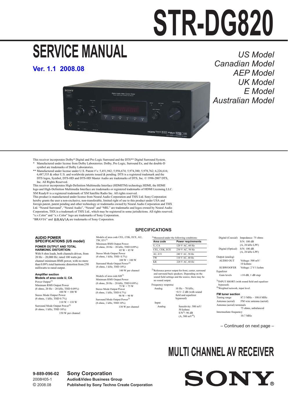
Sony str dg 820 service manual

This is the 122 pages manual for sony str dg 820 service manual.
Read or download the pdf for free. If you want to contribute, please mail your pdfs to info@audioservicemanuals.com.

Page: 1 / 122
left right
sony str dg 820 service manual

Extracted text from sony str dg 820 service manual (Ocr-read)


Page 2

STR-DG820
Ver. 1.1

AM tuner section
Tuning mnge

Area code Tuning scale
10 kllz step 9 kllzslep
ucA Slokllzr 531 kllzr
1.7101(111 1710x112"
(EL CEK. ECE , 531 kllzr
1 hoz kllz
AU,E51 Slllkllzr 511 kllz ,7
1,710 Mir 1.710 kllz
KR,TW 5111 kllzr 531 kIIZr

1.510 klle 1.6112 kllz
Anlcnna (aerial) Loop anlcnna
lnrcnncdiate frequency
450 kHz
You can change rhe AV] [Inning scale 10 9 kllz or
in kllz Aher mnlng in any AM station, turn on
rhe lecelvel While holding down TUNlMr
MODE, pier: POWER eh rhe receiver All preser
srallonswlll be erased when you change rhe tuning
scale To mscl rhe scale ro ID kllz (or 9 kl lz).
repem rhe procedure
Video section
lriphrs/Oulphls
Videe. 1 Vprp, 75 ohms
COMPONENT VIDEO.
v. 1 Vprpr 75 ohms
Ifl/(n 0 7 Vprp. 75 ohms
lwch. 0 7 Vprpr 75 ohms

30 MHz HD 1m»- Through
General

Iower requllemenls

Area code Power requiremema

L'. A l20VAC,60IlZ
CELCEKrECE ZZDVAC,SII 60 Z
W
TW IIOVAC.60IIZ

KR 721 730 V AC $015011:

Power umpul lDlGlTAL MEDIA PORT)
DC OUT 5V. 0,7 A MAX

Iowel conwmpllon

Area code Pawercnnsumplion

u 250 w
CA 320 VA
CEL. CEK. ECE. 230 w
AL. KR. ESI

Tw 2211 w

Powel consumphon (Llunng standby mode)
0 7 w
(When CTRL'HDMI" in
HDMI menu is set to
CTRL on")
Dimenslom 1eirllh,lieighmleplhl (Approx)
17 x 61/4 x 12 "3 Inches
(410 x 157 5
including plowchng [inns
and controls
Mass (Approx) 1x11: 12 oz (8 5 kg) (U. CA)
3 4 kg (CEL. can,
E(E.AU1TW. KR. 5511

Supplied accessories

Opemling lnshuchum

other Semp Guide 111

FM wrre antennil (11911111) «1)

AM loop nnlenna (nennll (1)

Remote commandcl (kMrAAlDZ l) (11
Rs lsizeAA) hmrerres (2)

Ophmlzel microphone (ECMVACZ) 111

Design and specifications are subjccr re
change without neiiee

About area codes

The area code or the receiver you purchased is
shown on the lower nghl portion at the rear panel
(see me illustration below),

3-xxx-xxx-xx AA

Area code

Any differences in operahon. assuming to the area
eede, are clearly indicated in the text, forexample,
"Models at area eede AA ehly".

Notes on chip component replacement

- Never reuse a disconnected chip component.

- Notice that the minus side ofa tantalum capacitor may be dam-
aged by heat.

SAFETY CHECK-OUT

After correcting the original service problem, perform the follow-
ing safety check before releasing the set to the customer:

Check the antenna terminals, metal trim, metallized knobs,
screws, and all other exposed metal parts for AC leakage.

Check leakage as described below.

LEAKAGE TEST

The AC leakage from any exposed metal part to earth ground and

from all exposed metal pans to any exposed metal part having a

return to chassis, must not exceed 0.5 mA (500 microamperes.).

Leakage current can be measured by any one of three methods.

1. A commercial leakage tester, such as the Simpson 229 or RCA
WT-540A. Follow the manufacturers instructions to use these
instruments.

2. A battery-operated AC milliammeter. The Data Precision 245
digital multimeter is suitable for thisjob.

3. Measuring the voltage drop across a resistor by means of a
VOM or battery-operated AC voltmeter. The limit indication
is 0.75 V, so analog meters must have an accurate low-voltage
scale. The Simpson 250 and Sanwa SH-63Trd are examples
ofa passive VOM that is suitable. Nearly all battery operated
digital multimeters that have a 2 V AC range are suitable. (See
Fig. A)

To Exposed Metal
Parts on Set
AC
0.1511F g 1.5 kn / voltmeter
(0.75 V)

_7_ Earth Ground
Fig. A. Using an AC voltmeter to checkAC leakage.

SAFETY-RELATED COMPONET WARNING!

COMPONENTS IDENTIFIED BY MARKAOR DOTTED LINE
WITH MARKAON THE SCHEMATIC DIAGRAMS AND IN
THE PARTS LIST ARE CRITICAL TO SAFE OPERATION.
REPLACE THESE COMPONENTS WITH SONY PARTS
WHOSE PART NUMBERS APPEAR AS SHOWN IN THIS
MANUAL OR IN SUPPLEMENTS PUBLISHED BY SONY.

ATTENTION AU COMPOSANT AYANT RAPPORT
A LA SECURITE!

LES COMPOSANTS IDENTIFIES PAR UNE MARQUE ASUR
LES DIAGRAMMES SCHEMATIQUES ET LA LISTE DES
PIECES SONT CRITIQUES POUR LA SECURITE DE FONC-
TIONNEMENT. NE REMPLACER CES COM- POSANTS QUE
PAR DES PIECES SONY DONT LES NUMEROS SONT DON-
NES DANS CE MANUEL OU DANS LES SUPPLEMENTS
PUBLIES PAR SONY.