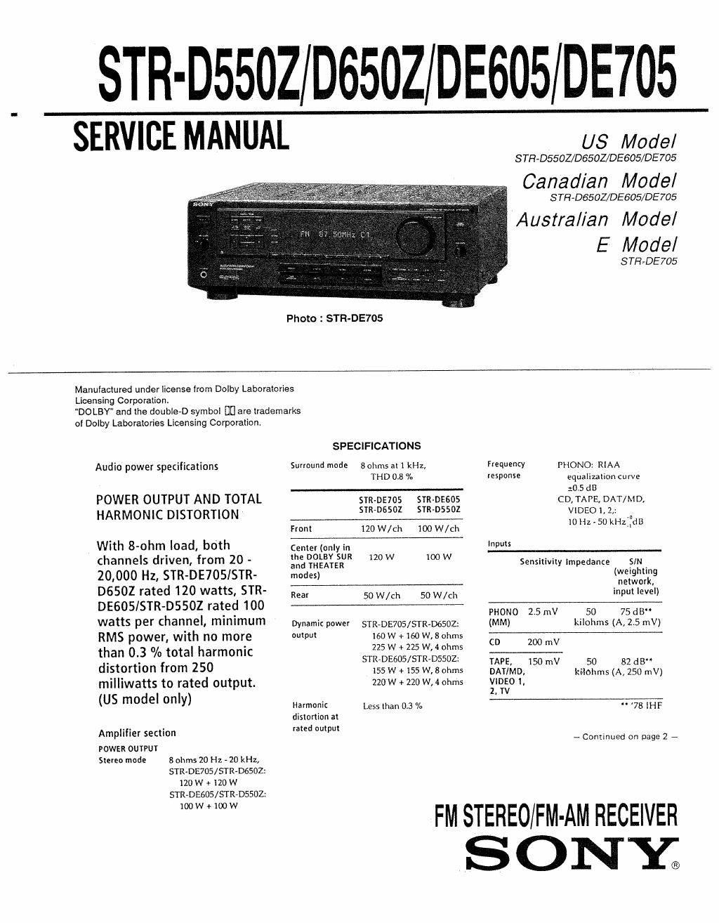
Sony str de 705 rec service manual

This is the 33 pages manual for sony str de 705 rec service manual.
Read or download the pdf for free. If you want to contribute, please mail your pdfs to info@audioservicemanuals.com.

Page: 1 / 33
left right
sony str de 705 rec service manual

Extracted text from sony str de 705 rec service manual (Ocr-read)


Page 1

STR-D5502 D6502 DE605 DE705

SERVICE MANUAL

US Model

S TR-DS5OZ/D6SOZ/DE605/DE 705

Canadian Model

S TH-DSSOZ/DESOE/DE 705

Australian Mode/

E Model

STE-DE705
Photo 2 STR-DE705
Manufactured under license from Dolby Laboratories
Licensing Corporation.
"DOLBY" and the double-D symbol DU are trademarks
of Dolby Laboratories Licensing Corporation.
SPECIFICATIONS
Audio power specifkations Surround mode 30th all kHz, Frequencv PHONO: RIAA
THD 0.8 % response equalization curve
:05 an
POWER OUTPUT AND TOTAL STR-DE7OS snMJEsos co, TAPE, DAT/MD,
HARMONIC DISTORTION mm 55" VIDEO I, 2»
v.7
Front 120 W/ch 100 W/ch 10quer kHZIdB
Wlth 8-ohm load, both Center (only in Inputs
channels driven, from 20 - :figgfitgéfl OW 100w Sensitivity lmpedance §IN
20,000 HZ, STR-DE705/STR- modes) (wstrgigl'lcg
n W ,
- r te
D 6 5 a . . PHONO 2.5 mV 50 75 dB
watts per channel, minimum Dynamic power sTR-DE705/STR-DGSOZ: (MM) kilohms (A15 mV)
RMS power, Wlth no more output 160w +160W,8ohms CD 200 v
. m
than 0.3 °/o total harmonic 225W + 5 4°th -_
distortion from 250 STR-DE605/STR-DSSOZ: PE, 150 mV 50 32 018..
_ . 155 w + 155 w, 8 ohms DAT/MD. ki-Ichms (A, 250 mV)
mllllwatts to rated output. 220w + 220 w, 4 ohms gigs/o 1,
(US mOdeI only) Harmonic Less man 03 % " '78 IHF
dislorlion at

Amplifier section

POWER OUTPUT
Stereo mode 8 ohms 20 Hz - 20 kHz,
STRvDE705/STR-DGSOZ:
120 W + 120 W
STR~DESDSISYRAD5502

100W+100W

rated output

- Continued on page 2 -

FM STEREO/F M- AM RECEIVER

SONY

Page 2

Outputs

Mining
BASS BOOST

'lONE

REC OUT VIDEO I, 2
(AUDIO) OUT:
Voltage 150 mV,
Impedance 10 kilohms

MIX OUT
Voltage: 2 V
Impedance: 1 kilohms

HEADPHONES: Accepts
low and high

FM tuner section

Tuning range

Antenna
terminals

Sensitivity

Usable sensitivity
SIN

Harmonic
distortion at

1 kHz

Separation

Frequency
response

Selectivity

AM tuner section

With 10 kHz interval:
530 - 1710 kHz

With 9 kHz interval:
531 - 17l0 kHz

tuning range

Antenna Loop antenna

Usable sensitivity 50 dB/rn (at 1,000 kHz or

Power Australian model:
requirements 240 V AC, 50 Hz
US. Canadian. Emodel :
120 V AC, 60 Hr.
Power STR-DE705/5I'R-D6502:

consumption US. E. model : 230 W
Canadian model: 325 VA

Australian Model: 230 W

im edance STR»DE605/STR>DSSUZ:
P 999 kHz)
headphones US. E model : 220 W
SIN 54 dB (at 50 mV/rn) Canadian model: 320 VA
- 20 dB
Harmonic 0.5 9:. (50 mV /m, 400 kHz) AC outlets Australian model:
l 10 dB at 70 Hz distortion usév":',°d'e°d:?° w
. ana Ia". mo 1
28 48 al 00 Hz and Selectivity At 9 kHz: 35 dB 2 mm" I '20 W
10 kH . .
z N '0 RHL 4° 3 Dimensions 430 x 157 x 355 mm
You can change the AM tuning interval to 9 (17 x 6 V. x H inches)
kHz, After tuning in any AM station, turn
37-5 ' 8" MHZ off the receiver. Hold down the PRESET Mass (Approx) STR-DE705/5TR-D650Z:
75 t b I d TUNING + button and press the POWER 10,0 kg (22 lb 1 01)

° "5' u" a 3" button. All preset stations will be erased srnoeeos/srnossoz;
when you change Ihe interval. To reset the 97 kg (22 lb 7 oz)
interval to 10 kHz, repeat the procedure,

M°"°i_ 83 dBf' 45 V . . Supplied FM wire antenna (t)
5'2'90' 38'3 dBf 5 "v Video seam" accessories AM loop antenna (1)
Inputs VIDEO 1, 2, TV: Remote commander
1L2 dBf,2uV (IHF) IVP'P 75 ohms (remote) (1)
Size AA (R6) batteries (2)
Mono: 76dB Outputs VIDEO 1, 2, MONITOR: Audio/Video cable (I)
5'9 7° d 1 VP-P 75 ohms (us and Canadian and e
STR-DE705 only)
1 i %
Mono. 0 3 General Control S cord (I)
5'890- 05 % System Tuner section: ILL (US and Canadian and E
quartz-locked digital SlR-DE705 only)
45 dB at 1 kHz SylII?>"zm 5PM Design and specifications are subject to
Preamplifier sectron: Low- . l
. . change WIIhout "(NICE

.0, muse NF type equallzer

30 H2 - 15 kHz -2 dB Power amplifier section:
Pure-complimentary SEPP
60 dB at 400 kHz
TABLE OF CONTENTS
specifications ............................................................... 1
1. GENERAL ............................................................. 4

2. EXPLANATION~

'0 TERMINALS -

3. DIAGRAMS .
3.1 Circuit Boards Location .. ..................................... 9

3-2. Printed Wiring Boards (Surround Section)
3-3. Schematic Diagram (Surround Section)
3-4. Schematic Diagram ( AP Section)
3-5i Printed Wiring Boards (AMP Section) ~~~~~~
3-6i Schematic Diagram (Display Section)
3-7. Printed Wiring Boards (Display Section)-

4. EXPLO'JED VIEWS

4 1. Front Panel Section -
.1 7. Chassis Section ..

5, ELECTRICAL PARTS LIST ................................... 35

_2..__