Sony str da 9000 es schematic 1

This is the 44 pages manual for sony str da 9000 es schematic 1.
Read or download the pdf for free. If you want to contribute, please mail your pdfs to info@audioservicemanuals.com.

Page: 1 / 44
left right
sony str da 9000 es schematic 1

Extracted text from sony str da 9000 es schematic 1 (Ocr-read)


Page 1

NOTE:

- Due to standardization, replacements in the
parts list may be different from the parts ,
fied in the diagrams or the components used
on the set.

- -XX and -X mean standardized parts, so they
may have some difference from the original
one.

RESISTORS
All resistors are in ohms.

METAL: Metal-film resistor.

ci-

SECTION 8

ELECTRICAL PARTS LIST

- Items marked * are not stocked since they

are seldom required for routine service.

Some delay should be anticipated when order-
ing these items.

SEMICONDUCTORS
In each case, u: [L for example:

A. . : 11A. .
uPB. . :uPB. .
uPD. . :pPD. .

' CAPACITORS

METAL OXIDE: Metal oxide-film resistor. uF: 11F
F: nonflammable - COILS
H: H
Ref. No. Part No. Description Remark
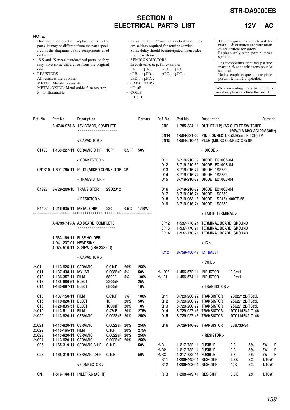
A-4748-975-A 12V BOARD, COMPLETE
< CAPACITOR >
C1496 1-163-227-11 CERAMIC CHIP 10PF 0.5PF 50V
< CONNECTOR >

CN1310 1-691-765-11

PLUG (MICRO CONNECTOR) 3P

< TRANSISTOR >
01323 8-729-209-15 TRANSISTOR 2SD2012
< RESISTOR >
R1492 1-216-635-11 METAL CHIP 220 0.5% 1/10W
A-4733-745-A AC BOARD, COMPLETE
*******************
1-533-189-11 FUSE HOLDER
4-941-237-01 HEAT SINK
4-974-510-11 SCREW (+BV 3X8 CU)
< CAPACITOR >
AC1 1-113-925-11 CERAMIC 0.01uF 20% 250V
C11 1-137-438-11 MYLAR 0.0082uF 5% 50V
C12 1-136-357-11 FILM 680PF 5% 100V
C13 1-135-686-51 ELECT 2200uF 25V
C14 1-135-697-11 ELECT 6800uF 16V
C15 1-137-150-11 FILM 0.01 uF 5% 100V
C16 1-119-820-11 ELECT 1uF 20% 50V
C18 1-128-835-51 ELECT 1000uF 20% 10V
AC19 1-113-511-11 FILM 0.47uF 20% 275V
AC20 1-113-920-11 CERAMIC 0.0022uF 20% 250V
AC21 1-113-920-11 CERAMIC 0.0022uF 20% 250V
AC22 1-115-165-11 FILM 0.1uF 20% 275V
AC23 1-113-920-11 CERAMIC 0.0022uF 20% 250V
AC24 1-113-920-11 CERAMIC 0.0022uF 20% 250V
C25 1-165-319-11 CERAMIC CHIP 0.1uF 50V
C26 1-165-319-11 CERAMIC CHIP 0.1uF 50V
< CONNECTOR >
CN1 1-816-148-11 INLET, AC (AC IN)

uPA. . : PA. .
uPC. . : UPC. .
Rel. No. Part No.
CN2 1-785-834-11
CN14 1-564-321-00
CN15 1-564-510-11
D11 8-719-210-39
D12 8-719-210-39
D13 8-719-016-74
D14 8-719-016-74
D15 8-719-210-39
D16 8-719-210-39
D17 8-719-016-74
D18 8-719-053-18
D19 8-719-016-74
EP12 1-537-770-21
EP13 1-537-770-21
EP14 1-537-770-21
IC12 8-759-450-47
A LF02 1-456-572-11
A LF1 1-456-574-11
O11 8-729-200-72
O12 8-729-200-72
O13 8-729-200-72
O14 8-729-027-43
O15 8-729-027-43
O16 8-729-140-93
AR1 1-217-782-11
AR2 1-217-782-11
AR3 1-217-782-11
R11 1-208-445-41
R12 1-208-462-41
R13 1-208-449-41

STR-DAQOOOES

12V AC

The components identified by
mark A or dotted line with mark
A are critical for safety.

Replace only with part number
specified.

Les composants identifies par une
marque A sont critiquens pour la
sécurité.

Ne les remplacer que par une piéce
portant le numéro spécifié.

When indicating parts by reference
number, please include the board.

Description Remark

OUTLET (1 P) (AC OUTLET SWITCHED
120W/1A MAX ACIZOV 60Hz)

PIN, CONNECTOR (3.96mm PITCH) 2P

PLUG (MICRO CONNECTOR) 6P

DIODE
DIODE
DIODE
DIODE
DIODE

EC1OOS-04
EC1008-04
188352
188352
EC1008-04

DIODE
DIODE
DIODE
DIODE

EC1008-04
188352
18R154-400TE-25
188352

< EARTH TERMINAL >
TERMINAL BOARD, GROUND

TERMINAL BOARD, GROUND

< IC >

IC BA05T

< COIL >

INDUCTOR 3.3mH
INDUCTOR 1.2mH

< TRANSISTOR >

TRANSISTOR 28C2712L-TE85L
TRANSISTOR DTC114EKA-T146
TRANSISTOR 283733-34

FUSIBLE 3.3 5% 5W F
FUSIBLE 3.3 5% SW F
FUSIBLE 3.3 5% SW F
RES-CHIP 2.2K 2% 1/10W
RES-CHIP 10K 2% 1/10W
RES-CHIP 3.3K 2% 1/10W

159