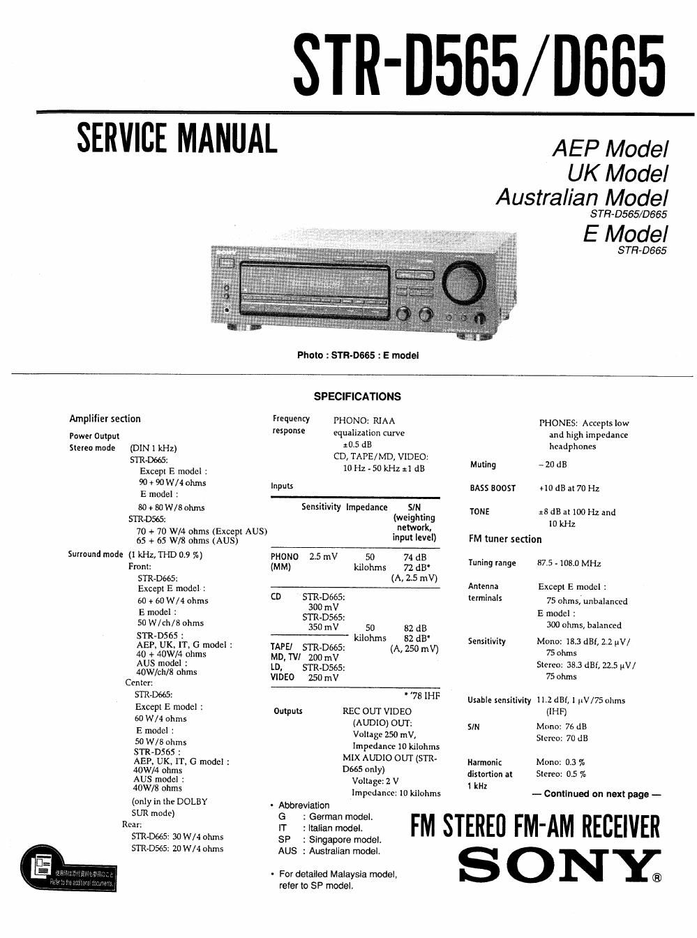
Sony str d 665 service manual

This is the 39 pages manual for sony str d 665 service manual.
Read or download the pdf for free. If you want to contribute, please mail your pdfs to info@audioservicemanuals.com.

Page: 1 / 39
left right
sony str d 665 service manual

Extracted text from sony str d 665 service manual (Ocr-read)


Page 2

Separation 45 dB at l kHz

Dimensions Except E model :
430 x I35 x 300 mm

Frequency 30 Hz - 15 kHz jsdB (17 x 5 3/8 x 11 3/4 inches)
response E model 1

430 x135 x 295 mm
Selectivity 60 dB at 400 kHz Mass (Approx.) STR-D665 :

AM tuner section
Tuning range 531 - 1602 kHz
Antenna Loop antenna

Usable sensitivity 50 dB/m (at 999 kHz)

AEP, UK, IT. G, AUS model : 7.0 kg (15 lb 7 oz)

E, SP model : 6.9 kg
STR»D565 :
6.2kg (I3 lb 11 oz)

Supplied accessories FM win: anlcnna (1)
AM loop antenna (I)
Remote commander
(remote) (I)
Size AA (R6)
batteries (2)

SIM 54 dB (at 50 mV/m) Design and specifications are subject to
change without notice
Harmonic 0.5 In (50 mV/ m,
distortion 400 kHz) . Abbreviation
G 2 German model.

Selectivity Except E model 2 35dB 'T 1 We" "we-

E model ; SP : Singapore model.

Ar 9 kHz : 35dB AUS : Australian model.

At 10 kHz : 40dB

(E model ONLY)

You can change the AM tuning interval
to 9 kHz or 10 kHz, After tuning in any
AM station, turn off the receiver. Hold
down the PRESET TUNING + button
and press the POWER button. All preset
stations will be erased when you change
the interval. To reset the interval to ID
kHz or 9 kHz, repeat the procedure.

Video section

Inputs VIDEO, TV/LD:
I Vp-p 75 ohms

Outputs VIDEO MONITOR
I Vp-p 75 ohms

- For detailed Malaysia model,
refer to SP model.

TABLE OF CONTENTS

m m Earle

SERVICING NOTE

TEST MODE .................................................................... 3
SECTION 1. GENERAL .................................................. 4

SECTION 2. DlSASSEMBLY
2-1. Case and Front Panel
2-2. Display and Tone Board
243. Back Panel
2-4. SP SW Board
2-5. Main Board


Nwmmwm

Gene'al 24;. Motor vn, VOL-Main and Video-Main Board.
System Tuner section: PLL
quartz-locked SECTION 3. DIAGRAMS
digital synthesizer 3-1. Circuit Boards Location
system 3-2. Printed Wiring Board - Main Section -
Preamplifier section; 3-3. Schematic Diagram - Main Section - . 13
Low-noise NF Iy'pe 3-4. Printed Wiring Board - Display Section - 17
equalizer 3-5. Schematic Diagram - Display Section - . 21

Power amplifier
section: Pure-
complimentary
SEPP
Power requirements AEP, UK, IT, G, SP model :
220 - 230 V AC, 50/60 Hz
AUS model :
240V AC, 50/60 Hz
E model :
120/220/240 V AC. 50/60 Hz
Powerconsurnption STR-D665z
AEP. UK, SP model :
200 W
E. AUS model :
170 W
SIR-D565 :
AEP, UK. IT, G. model :
160W
AUS model :
140W
AC outlet AEP, E, IT, G. AUS model :
Switched 100W

3-6. IC Block Diagrams ....................................
3-7. to Pin Function
0 l0201 (pPD78044GF-126-389)

SECTION 4. EXPLODED VIEWS

4-1. Case and Front Panel Section ........... L ..................
4-2. Chassis Section ..
4-3. Main Board Section

SECTION 5. ELECTRICAL PARTS LIST....

SAFETY-RELATED COMPONENT WARNING ll

COMPONENTS IDENTIFIED BY MARK A OR DOTTED

LINE WITH MARK A ON THE SCHEMATIC DIAGRAMS
AND IN THE PARTS LIST ARE CRITICAL TO SAFE

OPERATION. REPLACE THESE COMPONENTS WITH
SONY PARTS WHOSE PART NUMBERS APPEAR AS
SHOWN IN THIS MANUAL OR IN SUPPLEMENTS
PUBLISHED BY SONY.

___2_