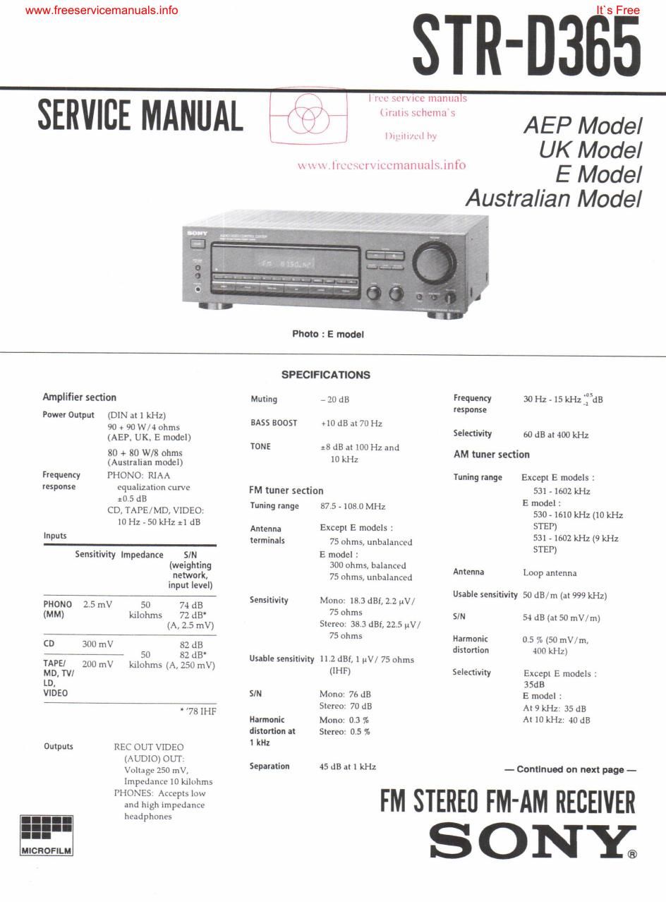
Sony str d 365 rec service manual

This is the 27 pages manual for sony str d 365 rec service manual.
Read or download the pdf for free. If you want to contribute, please mail your pdfs to info@audioservicemanuals.com.

Page: 1 / 27
left right
sony str d 365 rec service manual

Extracted text from sony str d 365 rec service manual (Ocr-read)


Page 2

www.freeservicemanuals.info

(E model ONLY)

You can change the AM tuning interval
to 9 kHz or IO kHz .

After tuning in any AM station, turn off
the receiver. Hold down the PRESET
TUNING + button and press the POWER
button. All preset stations will be erased
when you change the interval. To reset
the interval to 10 kHz or 9 kHz. repeat

the procedure.

General

System

Power
requirements

Power
mnsumptlon

Dimensions

Mass (Approx)

Su pplled
accessories

Tuner semen: ILL
quartz-locked digital
synthesizer system

Preamplifier section:
LowAnoise NF type
equalizer

Power amplifier section:
Pure-complimentary
SEPP

Except E models :
220 - 230 V AC
50/60 Hz
E model :
120/220/240 V AC,
50/ 60 Hz
E. Singapore,
Malaysia.
HongKong model :
200 W
AEP, UK. German.
East European.
Australian : 180W
Except E models :
430 x 135 x 300 mm
E model :
430 x I35 x 295 mm

Except UK models :
6.8 kg
UK model : 7.0kg

FM wire antenna (1)

AM loop antenna (1)

Remote commander
(remote) (I)

Size AA (R6) batteries (2)

Design and specifications are subject to
change without notice.


llS Free
TABLE OF CONTENTS

Sggjign '1 e Baas
SERVICE NOTE .............................................................. 3
TEST MODE ,. 3
SECTION 1. GENERAL ................................................. 4
SECTION 2. DISASSEMBLY
2-1. Case and Front PaneI 5
22. Display and Tone Board 5
2-3. Back Panel . 6
274. SP SW Board 6
2-5. Main Board. 7
2-6. VOL and VOL-MAIN Connect Board. 7
SECTION 3. DIAGRAMS
3'1. Circuit Boards Location ...................... B
3-2. Printed Wiring Board - Main Section - 9
373 Schematic Diagram - Main Section - 13
3-4. Printed Wiring Board - Display Section - 17
3-5 Schematic Diagram -- Display Section - . 21
3-6. It: Pin Function

- IC201 (pPD?80446F»126-389).w....,..._........................23

SECTION 4. EXPLODED VIEWS
4-1. Case and Front Panel Section
4-2. Chassis Section
4-3. Main Board Section

SECTION 5. ELECTRICAL PARTS LIST ....................... 28

SAFETY-RELATED COMPONENT WARNING II

COMPONENTS IDENTIFIED BY MARK A OR DOTTED

LINE WITH MARK A ON THE SCHEMATIC DIAGRAMS
AND IN THE PARTS LIST ARE CRITICAL TO SAFE

OPERATION. REPLACE THESE COMPONENTS WITH
SONV PARTS WHOSE PART NUMBERS APPEAR AS
SHOWN IN THIS MANUAL OR IN SUPPLEMENTS
PUBLISHED BY SONY.