Sony str d 350 z service manual
This is the 23 pages manual for sony str d 350 z service manual.
Read or download the pdf for free. If you want to contribute, please upload pdfs to audioservicemanuals.wetransfer.com.
Extracted text from sony str d 350 z service manual (Ocr-read)
Page 1
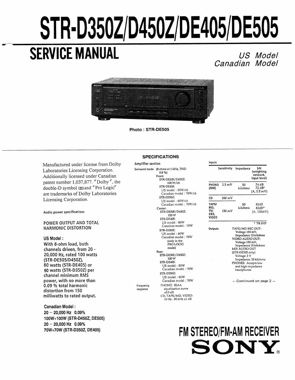
STR-D3502 D4502 DE405 DE505
SERVICE MANUAL U3 Model
Canadian Model
Photo I STR-DESOS
SPECIFICATIONS
Manufactured under license from Dolby Amplifier Section b-
Laboratories Licensing Corporation. Survound mode (83$n:)ailkHz,THD SensllMiy impedanze (waisglIIxing
Additionally licensed under Canadian From: mermaid!)
- : in u eve
patent number 1,037,877. Dolby , the 5 230:1]ng -V-l-
l . 2.
double»D symbol wand Pro Logic fififi . sow/Ch {£330 5 rn 13ng g; 3:.
are trademarks of Dolby Laboratories Canadian model : 70W/CII 25 "V)
' 5TR-D3SOZ:
Licensmg Corporation us model : wwmi CD 200 mV
Canadian model : 70W/ch TAPE! 50 sde
. . . Center: MD: kilohms 82cm
Audio pawer specificaiions menses/04502: Rials 150 mV (A, 150mv)
100W -
. SIR-DE405: 950
POWER OUTPUT AND TOTAL us model :80W 78"
Canadian model 1 70W
HARMONIC DISTORTION 311203502: Oulpul: TAPE/MD REC our;
S W1 ; 60" Xfifiiéinfffilmms
III/8 IIVIOdeliI l d b 9:133:32? W 35? AUDIO ourz
I . 0 age 150 mV,
t 8 o m_ 03 , 0th :3 LOCIC Impedance 10 kllohms
channels driven, from 20 ~ Rm m 9) MIX AUDIOOUT
20,000 Hz, rated 100 watts sin-02505204502: (SI/53:92?!
(STR-DESOSID4SOZ), wow in 25230:: imam
Sin-05406: mop V
so watts (STR-DE405) or us model :8ow ,fifighfifigsml
60 watts (STR-DBSOZ) per Silly; model 170 headphones
channel minimum RMS '
. us model :60W
power, With no more than Canadian model : 70w - (30,;an on page 2 _
009 % total harmonic Frequency mono RIAA
distortion from 150 (espouse equalilallon curve
. . OSdB
milliwatts to rated output. CDfTAPE/MDNIDEO:
)0 Hz - 50 kHz :1 dB
Canadian Model :
20 - 20,000 Hz 0.09%
loownoow (STR-D4502, 05505)
20 - 20,000 Hz 0.09%
7ownomsm-oasoz, DE405) FM STEREO/FM.AM RECEIVER
SONY?
Page 2
Muring Full mute
BASS BOOST n 10 dB at 70 HI.
TONE 28 dB at 100 Hz and
10 kHz
FM runer section
inning range 37:» 103,0 MHz
Antenna 75 ohms, unbalAnted
terminals 300 Ohms, unbalanced
Sensitivity Moxw: 183 ii, 45 pV
Stereo: 33.3 am, 45 nv
Usable Sensitivity in le, 2 51V (lHF)
SIN Mom): 76 dB
Stereo: 70 dB
Harmonia Mono: 0,3 A
distortion al Siereo: 0.5 %
1 kHz
Separaiion 45 an at 1 kHz
.0)
Frequtncy 30 Hz . l5 kl-lh dB
responxe
Seleuiviiy son!) at 400 kHz
AM tuner section
Tuning range mm w W inluval:
530 l7) kHz
With 9 kHz inlerval'
Usable sensilivily 50 dB/m (at 1,000 kHz or
999 ka)
3m 54dB(al50mV/m)
Harmonic 05 °/. (50 mV/m.
dixiorrion 100 kHz)
Seledivity At 9 kHz: 15 dB
A: ll) kHz: 40 dB
'- You can change me AM tuning interval
in 9 kHz. After Iuning in any AM mum
turn of! the receiver. Hold down (he
TUNING v buuun and press the POWER
button. All prewar surlons will be erased
when you change the lnlerval. To reset
rm lnrerval to 10 kHz. repent me
procedure.
Video section
lnpmx VlDEO,TV/DBS:
l Vp-p 75 ohms
Output: ViDEO:
le-p 75 ohms
MONITOR:
1 Vp-p 73 ohms
General
System Tuner section: PLL
quaru-lucked digilal
synthesizer system
Preamplifier sedion:
Law-noise NF rype
equalizer
Power amplifier section
Pure-complimentary
Vowu 120 v AC, 50 Hz
requiremeni:
Power STR-DESOS/D4SOZ
(onwmprion US model : 200W
Canadian model : 295VA
STR-DE405
US model : 165W
Canadian model : ZZSVA
STR-D3SDZ
US model : 150W
Canadian model 1 ZZSVA
AC oullels lswitched, total l20 W/
IA Max
Dimensions 430 x 1-18 x 295 mm
(17X57/X 1| lrinchcs)
Mass (Approx) STR~DE505/Dl5l)z,
7.3 kg (16 u: 101)
STR- DE405/ 03302.
65 kg (14 lb 5 oz)
Supplied FM wire antenna (l)
accessories AM loop amenna (l)
Ramble conlruller
(remote) (1)
Size AA (R6) batteries (2)
Design and specifications are subject in
change without noxice.
521 - 1710 kHz SEW
Antenna Loop anrenrui
TABLE OF CONTENTS
Section Title Page
specifications 1
1. GENERAL
Location and Function of controls
2. EXPLANATION OFIC TERMINALS~~~~~~~~~~~~ ------- ---6
3. DIAGRAMS
3.1~ Circuit Boards Location 8
3.2. Printed Wiring Boards (Main Section)~~ 9
3-3. Schematic Diagram (Main Section) 13
3%. Schematic Diagram (Display Section) - 18
3-5. Printed Wiring Boards (Display Section)"~~~~~~~~~~~~~~~ 21
4. EXPLODED VIEWS
4-1. Front panel Section
4-2, Chassis Section ~
5. ELECTR|CAL PARTS LIST26