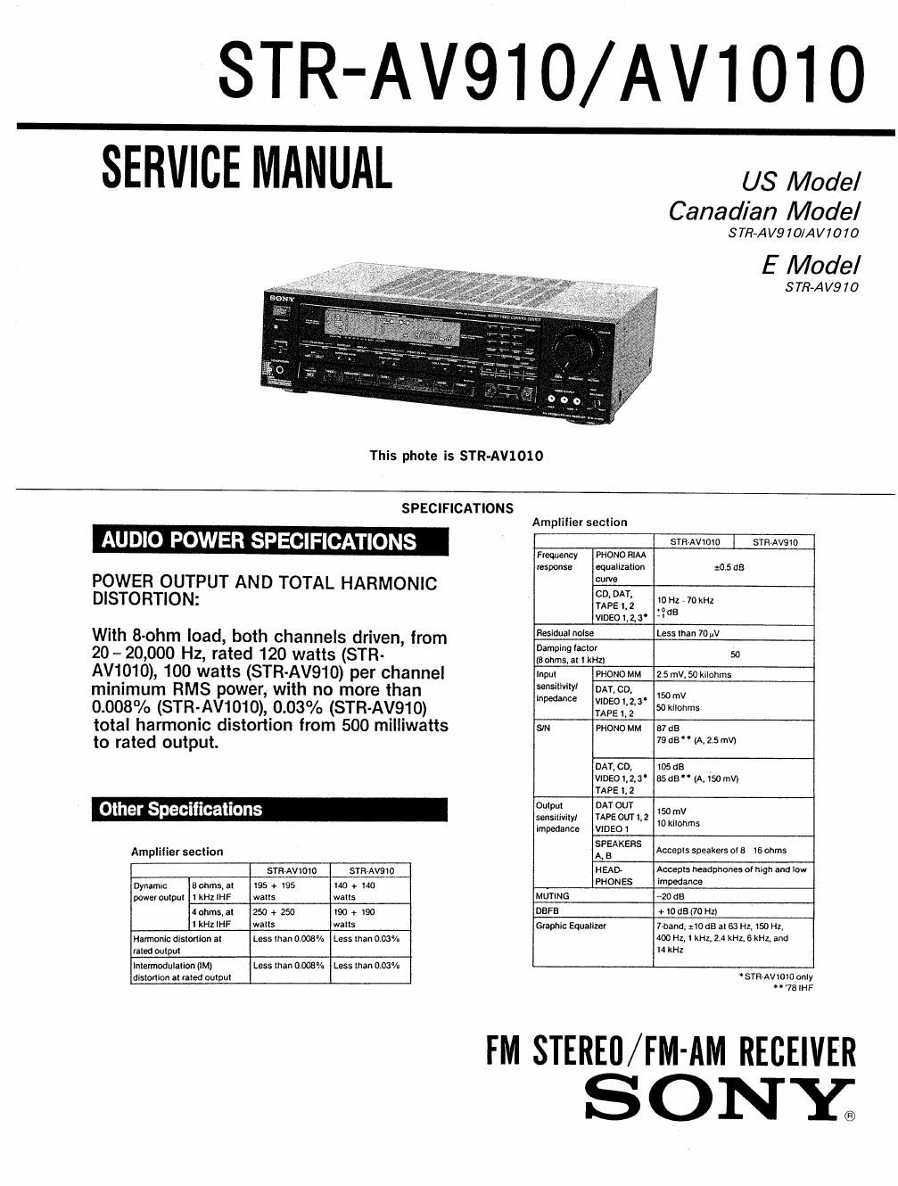
Sony str av 1010 service manual

This is the 33 pages manual for sony str av 1010 service manual.
Read or download the pdf for free. If you want to contribute, please mail your pdfs to info@audioservicemanuals.com.

Page: 1 / 33
left right
sony str av 1010 service manual

Extracted text from sony str av 1010 service manual (Ocr-read)


Page 1

STR-AV910/AV101O
SERVICE MANUAL Mode,

Canadian Model

STR-AVQ IO/AV70 70
E Model
S TR-AVQ 7 0
This phote is STR-AV1010
SPECIFICATIONS
Amplifier seclion
AUDIO POWER SPECIFICATIONS STR~AV1OIO STEM/90
Frequency PHONO RIM
Iesponse equalization :05 as
POWER OUTPUT AND TOTAL HARMONIC m
DISTORTION: $3,313 mm
' 'dB
VIDE01,Z3 4
With 8-ohm load, boh channels driven, from Resid0alnolse LessthanmuV
20 - 20,000 Hz, rated 120 watts (STR- 2322?;3152, 5°
AV1010), 100 walls (STR-AVQ'IO) per channel Inpul PHONOMM 2.5mV,50kilohms
mmlmum RMS power, With no more than fix: ogboo, . .me
0.003% (STR-AV1010), 0.03% (STR~AV910) 3953' 50mm
total harmonic distortion from 500 milliwatts sm PHONOMM me
lo rated output. MBWMSM
omen, mace
vmeoms' 8505"(A,150mV)
was 1,2
. . . 01 l DATOUT
Other Specifications gym mom: 30 mv
impedance vtosm mm
Amplifier section 23 Accepts Speakers on; lsohms
STRAVIDIO STRAVSIO HEAD ACCEDIS headphones cl hlgh and law
Dynamlc Bohms,at 195 + :95 no + no PHONES meme
powel oulpul IkHzIHF watts walls MUTING -20 as
40hms,a( 250 + 250 I90 + I90 DBFB + IOGBUO HZ)
l kHz IHF walls walls Glaphic Equalizer 7»bandv zIOdB al 63 Hz, I50 HZ,
Nannonic distortion 31 Less lhan 0.008% Less than 0.03% 400 H17 1 kHz, 24 kHz, 6 3011,3110
liled oulpul I4 kHz
IntermodulalioMlM) Less man 0.008% Lasslhan 0.03%
dislofliorl at Ialed oulpul STFl-AVIOIO only
"78IHF

FM STEREfl/FM-AM RECEIVER
SONY;

Page 2

STR-AV910/AV1010

Video section (STR-Av101o only) AM tuning section

inputs VIDEO 1,2, 3: Vp-p 75 onms smAvtoro I STR-AVQID
0mm WDEO ,' Momma: V 75 ohms Frequency range 530 , trio kHz twitn IO kHz interval)
531 4710 kHz (wim 9 kHz interval)
Antenna Loop antenna
' Usaote sensitivity so dBIm (a! tow RN: or 999 kHz)
FM tuner section er 5403(al50mwm)
STR-AVIOIO STR-AVSIO Harmonic otstonton 0.5% (50 mVlm, 400 Hz)
Frequency range 37.5 , moo MHz Selectivity 35 as (9 kHz) 40 es (lo kHz)
Antenna terminals 75 ohms coaxial 300 onmst oaisrreed Auto tuning threshold 55 dB/m
75 ohms, unbalanced
Sensitivity at 50 d8 13.3 cat, 45 pv (mono) G I
38.3 cat, 45 pv (stereo) enera
Usable sensitivily ".2 ant. 2 pv (IHF) smAVtoro I sm-Avoto
sm Mono 84 as at: dB Syslem Tuner section PLL quartz-locked digllaI synthesizer system
Stereo 75 ca 74 as Preamplifier Lownotse NF type equalizer
Harmonic Mono 0.27. o 3% Section
dislorlion al Stereo 04% o 5% Power Pure-complimentary SEPP
t kHz arnpiitier
IM distortion Mono 0.2% 0.3% mm?"
Stereo 04% 05% Power requirements 120 V AC, 60 Hz
Sewage" 45 d3 5 kHz Power consumption USA model: USA model E modal:
250watts Ziowaus 220
Frequency response $3125. 15 kHz ggsiaz » 15 kHz Canada model: Canada model: "5
. . 520 VA 450 VA
se'ecm'" . 65 as a' 30° '2 6° 3 z 00 1 Ac ouIIeis Two switched. lolal too watts
cam": '3' "2 5 Dimensions 430 x no it 350 mm
AM suppression ralio so on 54 do (,7 X 5.,_ x W, inches,
Image response ratio 80 dB 70 68
IF response ratio 90 as 70 as Weight 9 6 kg 9.5 kg 32021:?
Sprious Iesoonse Iallo too as so as at lb 3 oz) (2! lb) 15 mi
FIF intermoduiatton at 65 dB 50 as
600 m2 Supplied accessories
. FM ribbon antenna"), AM loop antenna (I)
$2323 L?" 30 oer Remote Commander ti), (RM-P201 ror srR-Avrow, RM-UIOO Ior STR-AV910)
9" 5° 5' Externar antenna connector (I) (STR-AVIOIO only),
Sony Batteries SUM-3(NSH?)
Design and specifications subject to change without notice.
TABLE OF CONT ENTS
Section Title ng2 Section Title Page
1. GENERAL 2-5. Schematic Diagram ~MAIN Section- ............ 17
1.1. Outline .......................................... 3 2-6. Schematic Diagram -DISPLAY Section- ........ 22
1-2. Connections . . ................................. 3 2-7. Printed Wiring Board ~DISPLAY Section- ...... 25
1-3. Parts Identification ....... 2-8. Printed Wiring Board -TUNER Section- ....... . i 27
1-4 Using the Remote Commander ..... . 7 2-9, Schematic Diagram -TUNER Section- .......... 29
2. DIAGRAMS 3. EXPLODED VIEWS
2-1. Semiconductor Lead Layouts ...................... 8 3-1. Front Panel Section . . . iiiiii 31
2-2. Circuit Boards Location .......................... 8 3-2. Chassis Section .................................. 32
2-3. Block Diagram .................................. 9
2-4. Printed Wiring Boards -MAIN Section- ........ 12 4. ELECTRICAL PARTS LIST ...... 34
5. ELECTRICAL ADJUSTMENTS . ..,.46

ATTENTION Au COMPOSANT AYANT RAPPORT
A LA sécunrrar

SAFETY-RELATED COMPONENT WARNINGI!
COMPONENTS IDENTIFIED BY MARK A OR DOTTED

LINE WITH MARK A ON THE SCHEMATIC DIAGRAMS
AND IN THE PARTS LIST ARE CRITICAL TO SAFE
OPERATION. REPLACE THESE COMPONENTS WITH
SONY PARTS WHOSE PART NUMBERS APPEAR AS
SHOWN IN THIS MANUAL OR IN SUPPLEMENTS PUB-
LISHED BY SONY.

LES COMPOSANTS IDENTIFIES PAR UNE MAROUE A
sun LES DIAGRAMMES SCHEMATIOUES ET LA LISTE
DES PIECES soNr CRITIQUES POUR LA sécunrré
DE FONCTIONNEMENT. NE REMPLACER css com-
POSANTS ours PAR oss PIECES souv DONT LES
numénos som Dormés DANS cs MANUEL ou
DANS LES SUPPLEMENTS PUBLIES PAR SONY.