Sony str a 37 rec service manual

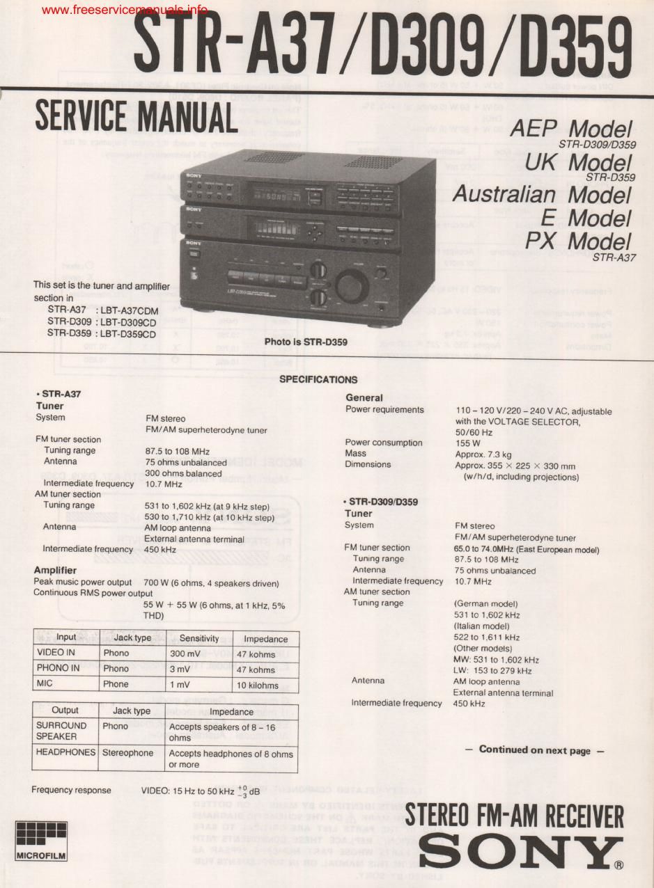
This is the 34 pages manual for sony str a 37 rec service manual.
Read or download the pdf for free. If you want to contribute, please mail your pdfs to info@audioservicemanuals.com.

Page: 1 / 34
left right
sony str a 37 rec service manual

Extracted text from sony str a 37 rec service manual (Ocr-read)


Page 2

www.freeservicemanuals.info

Amplifier
DIN power output 50 W + 50 W (6 ohms at 1 kHz)
Contlnuous RMS power output
60 W + 60 W 16 ohms. all kHz. 5%
THD)

Musrc power output 90 W + 90 W [6 ohms)

I Input Jack type I Sensitivtty Impedance .
I VIDEO IN Phone 300 mV 1 47 kohms

I PHONO IN I Phone 1 3 mV » d7 kohms

I Output I Jack type I Impedance

I SURROUND I Phone I Accepts speakers at 16 ohms

I SPEAKER I j

I Accepts headphones oi 8 ohms
of more

; HEADPHONES Stereophone

Frequency response VIDEO: 15 Hz to 50 kHz 1: dB

220 - 230 V AC. 50/60 Hz

150 W

Approx, 7.3 kg

Approx. 355 X 225 X 330 mm
(w/h/d. including prolecllons)

Power requirements
Power consumption
Mass

Dimensmns

Not. on Cor-mic FlltIr(CF301, A302, 303) Repllcomcnt.
(PANEL BOARD : D609, 0610)

This set employs two ceramic film (CI-30] , A302, 303) which
should have the same color marking to identify their center
frequency, therefore FM IF offset adjustment by (A. 3)
connection is necessary to match the center frequency of the
ceramic filters used with FM intcnnedialc frequency.

color marking

/
(cam. 302. 303)

ACF302 : G. [T model

0 :short
X :open
Ceramic litter Connection FM Intermediate
Color Cantu frequency 'A 'B 'me
mark (MHz) (D610) (D609) (MHz)
White 10,750 x 0 10750
Red 1 (1700 X X 10.700
Black 10.650 0 x 10.650
MODEL IDENTIFICATION

- Model Number Portion - STFl-A37, 0309, D359

S ONY' MODEL no;
FM STEREO/FM-AM RECEIVER

Ac://

AEP, G. IT, EE, CIS Model: 220-230V~50/60Hz 150W
UK Model: 240V~50Hz
E. AUS, PX Model:110-120V/220-240V~50/60Hz155W

Note:

G model : Germany model

IT model : Italian model

EE model : East European model

AUS model : Australian model

SAFETY

COMPONENTS IDENTIFIED BY MARK A OR DOTTED
LINE WITH MARK A ON THE SCHEMATIC DIAGRAMS
AND IN THE PARTS LIST ARE CRITICAL T0 SAFE
OPERATION. REPLACE THESE COMPONENTS WITH
SONY PARTS WHOSE PART NUMBERS APPEAR AS
SHOWN IN THIS MANUAL OR IN SUPPLEMENTS PUB-
LISHED BV SONY.

72,,