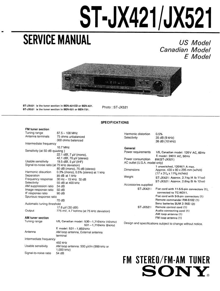
Sony ST JX521 Service Manual

This is the 16 pages manual for Sony ST JX521 Service Manual.
Read or download the pdf for free. If you want to contribute, please mail your pdfs to info@audioservicemanuals.com.

Page: 1 / 16
left right
Sony ST JX521 Service Manual

Extracted text from Sony ST JX521 Service Manual (Ocr-read)


Page 1

ST-JX421 JX521

SERVICE MANUAL

US Model
Canadian Model
E Model

514x421 is the tuner section in SEN-4210D or SEN-4211
STJX521 is the tuner section in SEN-521 or SEN-721.

Photo : ST~JX521

SPECIFICATIONS

FM tuner section
Tuning range
Antenna terminals

875 -- 108 MHz
75 ohms unbalanced
300 ohms balanced
intermediate frequency
107 MHz
Sensitivity (at 50 dB quieting )
22.1 der, 7 V (mono).
42.1 dBf. 70 1.1V (stereo)
Usable sensitivity 19.5 dBi, 5 p.V (lHF)
Signal-to-noise ratio (at 75 kHz deviation)
80 dB (mono). 75 dB (stereo)

Harmonic distortion 0.3% (mono). 0.5% (stereo) at 1 kHz

Separation 35 dB at 1 kHz
Frequency response 30 Hz - 15 kHz :28 dB
Selectivity 55 dB at 400 kHz

AM suppression ratio 54 dB

image response ratio 50 dB

IF response ratio 90 dB

Spurious response ratio
70 dB

Automatic tuning threshold
17.8 )1V (30 dBf)
Output 775 NW. 47 kohms (at 75 kHz deviation)
AM tuner section
Tuning range US, Canadian model: 530-1,710kH2 (tokHz)

531 -1,710kHz (9 kHz)
E model: 531 -1,602kHz

Antenna AM loop antenna, External antenna
terminal

Intermediate lrequency
450 kHz

Usable sensitivity AM loop antenna: 500 uV/m (999 kHz or
1,000 kHz)

SignaHo-noise ratio 54 dB

Harmonic distortion 0.5%
Selectivity 35 dB (9 kHz)

38 dB (10 kHz)
General

Power requirements US, Canadian model: 120V Ac, 60 Hz
E model: 240V AC, 50H:

Power consumption 8W($T~JX521)

AC outlet (U.S.A. model only)

1 unswitched, 120W/1 A max.

Dimensions Approx. 430 x 80 x 295 mm (w/h/d)
(17 x 31/4 x 115/3 inches)
Weight ST-JX421: Approx, 2.1 kg (4 lb 110:)

ST-JX521: Approx. 2.6kg (5 lb 1201)
Accessories supplied
ST-JX421 : Flat cord with 11-5-5-pin connectors (1),
connected to TC-W311.
Flat cord with 99-pin connectors 11)
Remote commander RM-SiOZ (1)
Sony batteries SUM 3 (NS) (2)
Remote control cord (1)
Audio connecting cord (1)
AM loop antenna (1)
FM loop antenna 11)

$T-JX521:

Design and specifications subject to change without notice.

FM STEREfl/FM-AM TUNER
S ON Y.

Page 2

ST-JX421/JX521

SAFETY CHECK~OUT TABLE OF CONTENTS
32mm title Rage
After correcting the original service problem,
perform the following safety check before releasing Specification ..........

the set to the customer:
Check the antenna terminals, metal trim, metallized

Safety Check-out


knobs, screws, and all other exposed metal parts for 1_ GENERAL
AC leakage. Check leakage as described below. 1-1. Location of Controls
1-2. Connections ~~~~~~~~~~~~~~~~~
LEAKAGE TEST
2. ELECTRICAL ADJUSTMENTS """""""""""""" 6
The AC leakage from any exposed metal part to
earth ground and from all exposed metal parts to any 3. DIAGRAMS
exposed metal part having a return to chassis, must 31 Printed Wiring Boards ......................................... 7
01 exceed 05 mA (500 microampers). Leakage 32. Schematic Diagrams (Tuner Section) N 11
cum can b9 measured by any one Of three 8-3. Semiconductor Lead Layouts ~~~~~~~~~~~~~~ 13
methods. 34 Wavefoms ........................................................ 13
I. A commercial leakage tester, such as the 3'5 Schematic Diagram
Simpson 229 or RCA WT-SAOA. Follow the (Control and Power Seam) """ 14
manufacturers instructions to use these instru-
ments. 4. EXPLODED VIEW ............................................... 17
2. A battery-operated AC milliammeter. The Data 6. ELECTRICAL PARTS LIST ................................ 19

Precision 245 digital multimeter is suitable for
this job.

3. Measming the voltage drop across a resistor by
means of a VOM or batterycperated AC volt-
meter. The limit" indication is 0.7SV, so
analog meters must have an accurate low-
voltage scale The Simpson 250 and Sanwa
SH-63Trd are examples of a passive VOM that

To change the AM tuning interval

The AM tuning interval is preset at the factory to 10 kHz
to match the frequency allocation system of your
country. To change the interval to 9 kHz, proceed as
follows.

1 Depress the POWER switch to turn on the unit.

2 Set the BAND FM/AM selectorto AM.

3 Press the POWER switch to turn off the unit.

4 Hold the TUNlNG knob in the + " position. and
depress the POWER switch to turn on the unit.
To reset the interval to 10 kHz, tollow the same
procedure.

is suitable. Nearly all battery operated digital
multimeters that have 3 2V AC range are
suitable. (See Fig. A)

Ta Exposed Metal
Part: on Set

AC
|: $1.5 ktl / voltmeter

(0t 75 V}
'._J

'5? Earth Ground

Note

When the interval is changed. all preset stations which
you have memorized using the numeric buttons will be
erased from the memory. Alter changing the interval, be
sure to preset the stations again,

0.15uF

Fig. A. Using an AC voltmeter to check AC leakage.

SAFETY-RELATED COMPONENT WARNING
COMPONENTS IDENTIFIED BV MARK A OR DOTTED

ATTENTION AU composmr AVANT RAPPORT
A LA SECURITEI

LINE WITH MARK A ON THE SCHEMATIC DIAGRAMS
AND IN THE PARTS LIST ARE CRITICAL TO SAFE
OPERATION. REPLACE THESE COMPONENTS WITH
SONY PARTS WHOSE PART NUMBERS APPEAR AS
SHOWN IN THIS MANUAL OR IN SUPPLEMENTS PUB-
LISHED 8V SONY.

LES COMPOSANTS IDENTIFIES PAR UNE MAROUE A
sun LES omonmmes SCHEMATIOUES ET LA usre
oss PIECES sour cmrtouEs mun LA sécumre
DE FONCTIONNEMENT. NE REMPLACER CES COM-
POSANTS QUE PAR DES PIECES SONV DONT LES
NUMEROS SONr DONNES DANS cs MANUEL ou
DANS LES SUPPLEMENTS PUBLIES PAR souv.