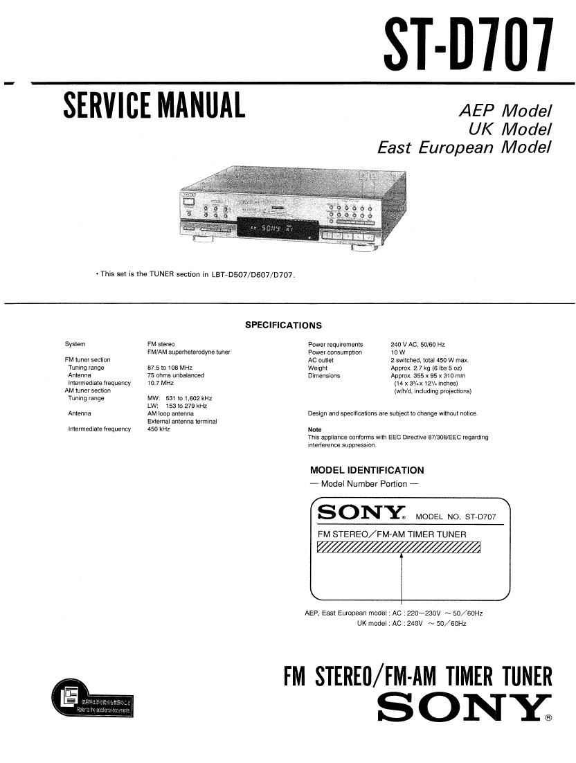
Sony ST D707 Service Manual

This is the 26 pages manual for Sony ST D707 Service Manual.
Read or download the pdf for free. If you want to contribute, please mail your pdfs to info@audioservicemanuals.com.

Page: 1 / 26
left right
Sony ST D707 Service Manual

Extracted text from Sony ST D707 Service Manual (Ocr-read)


Page 1

ST-D'IU'I

SERVICE MANUAL AEP Model

UK Model
East European Model

~ This set is the TUNER section in LBT»DSO7/DGO7/D707.

SPECIFICATIONS
System FM stereo Power requirements 240 V AC. 50/60 Hz
FM/AM superheterodyne tuner Power consumption 10 W
FM tuner section AC outlet 2 switched, total 450 W max.
Tuning range 87.5 to 108 MHz Weight Approx. 2.7 kg (6 lbs 5 oz)
Antenna 75 ohms unbalanced Dimensions Approx 355 x 95 x 310 mm
intermediate lrequency 10.7 MHz (14 x 33/x 12% inches)
AM tuner section (w/h/d. including projections)
Tuning range MW' 581 to l,602 kHz
LW: 153 to 279 kHz
Antenna AM loop antenna Design and specifications are subject to change without notice.
External antenna terminal
Intermediate frequency 450 kHz Note
This appliance conforms with EEC Directive 87/308/EEC regarding
Interference suppression.
MODEL IDENTIFICATION

- Model Number Portion -

SONYE MODEL NO, STaD707

FM STEREO/FM-AM TIMER TUNEFI

V////////////////////////////A

AEP, East European model 1 AC :220'280V ~ 50/6OHZ
UK model : AC :240V ~ 50/60Hz

FM STEREO/FM-AM TIMER TUNER
ONY;

Page 2

ST-D707
SECTION 1

GENERAL

This section is extracted
from instruction manual,

Location of Controls

SYSTEM POWER switch (8)

Buttons Io! sening the clock and timer (40. 42)
Display window

MEMORY bunon (14)

El E] El] MEMORYSCAN button (16)
AUTO TUNING button (12)
DISPLAY bunon (16,40)
i) a o o I km Numeric buttons (14)
(of o o o , \L BAND seiemor (12)
'== [-_! ST/MUTE button (i2)

TUNING +/- buttons (12)
SHIFT buttons (A, B, C) (14)
CHARACTER button (15)
Remote sensor

SLEEP button (41)

-fi

IEIEBEQ


@-

EEEJEIHEEEEEIEEEEB

71

SAFETY-RELATED COMPONENT WARNING

COMPONENTS IDENTIFIED BY MARK A OR DOTTED
LINE WITH MARK A ON THE SCHEMATIC DIAGRAMS
AND IN THE PARTS LIST ARE CRITICAL TO SAFE
OPERATION. REPLACE THESE COMPONENTS WITH
SONY PARTS WHOSE PART NUMBERS APPEAR AS
SHOWN IN THIS MANUAL OR IN SUPPLEMENTS PU8~
LISHED BY SONY.