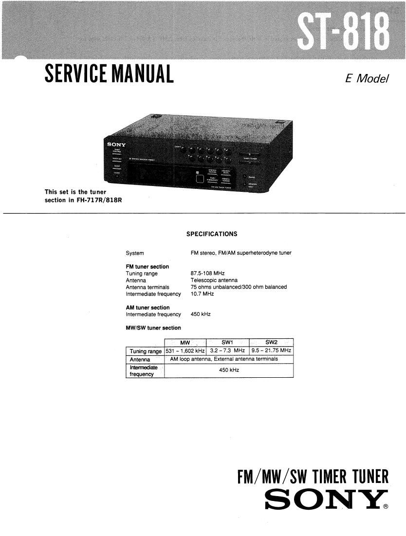
Sony ST 818 Service Manual

This is the 18 pages manual for Sony ST 818 Service Manual.
Read or download the pdf for free. If you want to contribute, please mail your pdfs to info@audioservicemanuals.com.

Page: 1 / 18
left right
Sony ST 818 Service Manual

Extracted text from Sony ST 818 Service Manual (Ocr-read)


Page 1

SERVICE MANUAL E/l/Iode/

This set is the tuner
section in FH-717R/818R

SPECIFICATlONS
System FM stereo, FM/AM superheterodyne tuner
FM tuner section
Tuning range 87.5408 MHz
Antenna Telescopic antenna
Antenna terminals 75 ohms unbalanced/300 ohm balanced

Intermediate frequency 10.7 MHz

AM tuner section
Intermediate frequency 450 kHz

MW/SW tuner section

MW \ SW1 SW2
Tuning range 531 -1,602 kHz 3.2 - 7.3 MHz 9.5 - 21.75 MHz
Antenna AM loop antenna, External antenna terminals
'Wae 450 kHz

frequency

FM/MW/SW TIMER TUNER
SONY;

Page 2

ST-8 1 8

0 Power supply for service
Since this machine has no power source in itself, the power is supplied form AMP TA-818 or TA-818M used for
this series.
As shown in the following table, this machine requires 4types of voltage, and supplying each type of voltage
separately makes complicated connections.
Accordingly, make connection with TA-818/ 818M at time of service, such as electrifying repair.
AC 3.9V FL-tube filament voltage
DC 724V Display controller IC701, grid voltage
DC 5V Display controller IC701, Vcc
DC 13V PLL control voltage
0 Service mode for checking the timer ON/OFF
1) Connect with AMP TA818/818M, and set the power switch of TA-818/818M to the state of STANDBY.
2) Set the time of tuner to a proper time (any time).
3) Press 3 switches simultaneously, namely, PRESET O, 6O and O BAND.
4) FL-tube display

All lamps lighting

l 1 sec.

10:23

l 0.5 sec.

10:24

i 0.5 sec.

_. POWER 0N

l 3 sec.

~Powm

5) End

-Caution for Service-
0 Reset of IC701

The display controller IC701 is reset by short-circuiting both edges of C702 (0.47;:F) while power OFF and
discharging electricity.

After resetting, the following frequencies are pre-set to the memory.

When the repair is completed, return the memory to the preceding state (content).

FM MW SW1 SW2

A1 87.5 MHz A6 531 kHz Bi. 3.2 MHZ B6 9.5 MHz

A2 88.0 MHZ A7 603 kHz 32 3.5 MHz B7 10.0 MHZ

A3 98.0 MHZ A8 999 kHz B3 5.0 MHz BB 15.0 MHZ

A4 100.0 MHZ A9 1,404 kHz B4 6.5 MHz B9 20.0 MHZ

A5 108.0 MHz A0 1,602 kHz BS 7.3 MHZ BO 21.75 MHz

SECTION 1
GEN ERAL
1-1. PARTS IDENTIFICATION
m TIMER SET bunon [E] TIME/FREQUENCY bunon
LEI [33 [4] La ill TIMER CONTROL switch TUNING/PRESET button
El Display window @ MEMORY/NEXT button
[I] PRESET STATION buttons BAND selector
OOOOOO l:| EI+/-bunons
5 O O O O O =21 II] MEMORY SCAN bunon
w :6 SLEEP button
N ; Dam-bl h CLOCK button
[2 STEREO/MUTING button
Remote sensor
Receives the remote-control signals.

[a] @[Ellfilhilfillfil

_2i