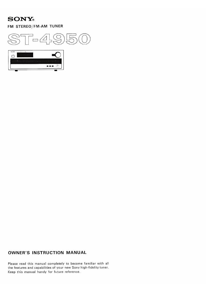
Sony ST 4950 Owners Manual

This is the 12 pages manual for Sony ST 4950 Owners Manual.
Read or download the pdf for free. If you want to contribute, please mail your pdfs to info@audioservicemanuals.com.

Page: 1 / 12
left right
Sony ST 4950 Owners Manual

Extracted text from Sony ST 4950 Owners Manual (Ocr-read)


Page 1

SONY®
FM STEREO/FM-AM TUNER

$T¢495©

OWNER'S INSTRUCTION MANUAL

Please read this manual completely to become familiar with all
the features and capabilities of your new Sony high-fidelitytunen
Keep this manual handy for future reference.

Page 2

TABLE OF CONTENTS

FEATURES ................. y ....... 2
WARNING ......................... Z
PRECAUTIONS ...................... 3
UNPACKING ........................ 4
SYSTEM CONNECTIONS .................. 4

Connection Notes
FM Antenna Connection
AM Antenna Connection
Output Connections
Connection Diagram
FM ANTENNAS ....................... 6
Multipath Reception
FM Antenna Orientation
LOCATION AND FUNCTION OF CONTROLS ........ 7
OPERATION ........................ 8
FM Reception
AM Reception
Adjustment of the Output Level

CARE OF YOUR EQUIPMENT ................ 9
Cleaning
Trouble Checks

SPECIFICATIONS ...................... 10

BLOCK DIAGRAM ..................... 1'l

WARNING

oTo avoid electrical shock, do not open the
cabinet. Refer servicing to qualified
personnel only.

0T0 prevent shock or fire hazard, do not
expose the'set to rain or moisture.

2

FEATURES

The 514950 is a highly sophisticated and sensitive fm stereo/
a-m tuner, designed with the most advanced Sony techniques
for discriminating audiophiles.

In the fm tuner section, a MOS FET front end, solid-state lF
filters and an IC IF amplifier assure not only excellent
selectivity and high sensitivity without distortion even in a
strong signal strength area, but a lower noise level and better
interference rejection.

The new Phase Lock Loop (PLL) FM Multiplex demodulator

IC stably ensures the greatest stereo separation and lowest
possible distortion.

Accurate and stable tuning is facilitated by using the new
type CG variable condenser. The Light Emitting Diode (LED)
dial indicator marks the desired stations sharply and precisely.

In the am tuner section, better interference rejection is
obtained by the use of a newly-developed IF filter. Also the
improved AGC circuit used in the RF block provides wide
input dynamic range and less distortion.

The strength of fm mUItipath signals. which so significantly
affects the quality of fm stereo reception, is visually indicated
to assist in adjusting the antenna direction for the clearest
signal.

A discriminator output jack is provided for any adaptors that
may be required in the future for discrete 4»channe| FM
transmissions.