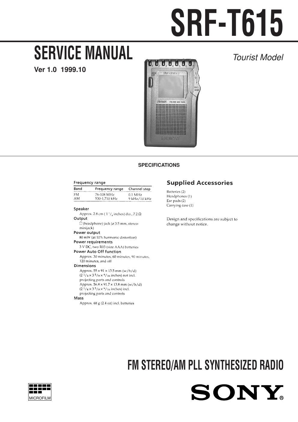
Sony srf t 615 service manual

This is the 14 pages manual for sony srf t 615 service manual.
Read or download the pdf for free. If you want to contribute, please mail your pdfs to info@audioservicemanuals.com.

Page: 1 / 14
left right
sony srf t 615 service manual

Extracted text from sony srf t 615 service manual (Ocr-read)


Page 1

Ð 2 Ð Specifications ........................................................................... 1 1. GENERAL Location and Function of Controls .................................... 2 2. DISASSEMBLY 2-1. Cover (JOG) (A) ......................................................... 3 2-2. Lid, Battery Case ........................................................ 3 2-3. Cabinet (Rear) ............................................................. 4 2-4. Main Board ................................................................. 4 3. ADJUSTMENTS .......................................................... 5 4. DIAGRAMS 4-1. Explanation of IC Terminals ....................................... 7 4-2. Block Diagrams .......................................................... 9 4-3. Printed Wiring Boards .............................................. 12 4-4. Schematic Diagram ................................................... 15 5. EXPLODED VIEW ..................................................... 19 6. ELECTRICAL PARTS LIST .................................... 20Flexible Circuit Board Repairing ¥ Keep the temperature of the soldering iron around 270¡C during repairing. ¥ Do not touch the soldering iron on the same conductor of the circuit board (within 3 times). ¥ Be careful not to apply force on the conductor when soldering or unsoldering. Notes on chip component replacement ¥ Never reuse a disconnected chip component. ¥ Notice that the minus side of a tantalum capacitor may be dam- aged by heat. TABLE OF CONTENTS SECTION 1 GENERAL LOCATION AND FUNCTION OF CONTROLS This section is extracted from instruction manual.

Page 2

Ð 3 Ð SECTION 2 DISASSEMBLY Note : Follow the disassembly procedure in the numerical order given. 2-1. COVER (JOG) (A) 2-2. LID, BATTERY CASE r The equipment can be removed using the following procedure. Cover (JOG) (A) Set Lid, Battery Case Cabinet (Rear) Main Board 1 Screw (B1.7x9) 2 Three claws 3 Turn from upper side of the cover (JOG) (A), and remove it. Cover (JOG) (A) 3 Two claws 1 2 Lid, battery cas e