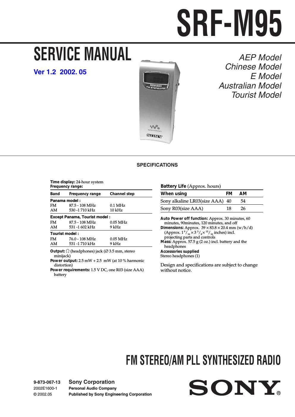
Sony srf m 95 service manual

This is the 16 pages manual for sony srf m 95 service manual.
Read or download the pdf for free. If you want to contribute, please mail your pdfs to info@audioservicemanuals.com.

Page: 1 / 16
left right
sony srf m 95 service manual

Extracted text from sony srf m 95 service manual (Ocr-read)


Page 1

2 SRF-M95 Notes on chip component replacement - Never reuse a disconnected chip component. - Notice that the minus side of a tantalum capacitor may be damaged by heat.Flexible Circuit Board Repairing - Keep the temperature of soldering iron around 270˚C during repairing. - Do not touch the soldering iron on the same conductor of the circuit board (within 3 times). - Be careful not to apply force on the conductor when soldering or unsoldering. SECTION 1 GENERAL This section is extracted from instruction manual. Setting the Clock The time display of this clock is a 24-hour system. 1 Press POWER to turn off the power. 2 Press and hold down the jog lever for more than 2 seconds until 0starts flashing. 3 Slide or keep sliding the jog lever up or down to adjust the hour and press the jog lever. If you keep sliding the jog lever up or down, the number changes rapidly. 0:00=midnight, 12:00=noon. 4 Slide the jog lever up or down to adjust the minutes and press the jog lever. : starts flashing and the clock starts operating. To set the current time exactly to the second, adjust the minute and then press the jog lever in time with a time signal (such as the telephone time signal). To cancel the setting, press MODE. Note Once you start setting the clock, you must perform each step within 60 seconds, or the clock setting mode will be cancelled. POWER Jog Lever (selection/decision) Molette (sélection/décision) Palanca de lanzadera (selección/decisión) MODE HOLD MEGA BASS Display Window Afficheur Visualizador 2 VOL Front Face avant Parte frontal

Page 2

3 SRF-M95 SECTION 2 DISASSEMBLY Note :Follow the disassembly procedure in the numerical order given. 2-1. MAIN BOARD, SUB BOARD 1 Screw (1.4 × 10) 1 Screw (1.4 × 10) 9 SUB board 7 Cover (Jack) 1 Screw (1.4 × 10) 5 Flexible board 4 Screw 6 MAIN board 3 Cabinet (front) assy 2 Six claws 8 Screw