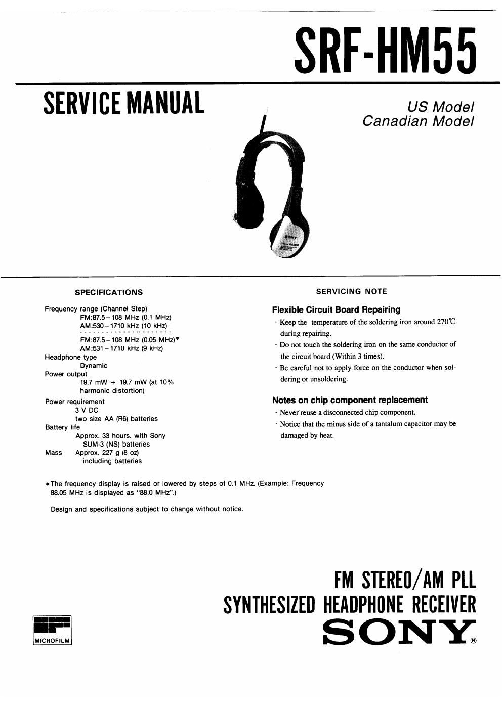
Sony srf hm 55 service manual

This is the 12 pages manual for sony srf hm 55 service manual.
Read or download the pdf for free. If you want to contribute, please mail your pdfs to info@audioservicemanuals.com.

Page: 1 / 12
left right
sony srf hm 55 service manual

Extracted text from sony srf hm 55 service manual (Ocr-read)


Page 1

SRF-HM55

SERVICE MANUAL

US Model
Canadian Model

MICROFILM

SPEClFICATIONS

Frequency range (Channel Step)
FM:87.5~108 MHz (0.1 MHz}
AM2530-1710 kHz (10 kHz)

FM:87.5-108 MHz (0.05 MHZ)
AM:531-1710 kHz (9 kHz)
Headphone type
Dynamic
Power output
19.7 mW + 19.7 mW (at 10%
harmonic distortion)

Power requirement
3 V DC
two size AA (R6) batteries
Battery life
Approx. 33 hours. with Sony
SUM-3 (NS) batteries
Mass Approx. 227 g (8 oz)
including batteries

SERVICING NOTE

Flexible Circuit Board Repairing
~ Keep the temperature of the soldering iron around 270°C
during repairing.
~ Do not touch the soldering iron on the same conductor of
the circuit board (Within 3 times).
- Be careful not to apply force on the conductor when sol-
dering or unsoldering.

Notes on chip component replacement
Never reuse it disconnected chip component.
' Notice that the minus side of a tantalum capacitor may be
damaged by heat

tThe frequency display is raised or lowered by steps of 0.1 MHz. (Example: Frequency

88.05 MHz is displayed as 88.0 MHz".)

Design and specifications subject to change without notice.

FM STEREfl/ AM PLL

SYNTHESIZEI] HEADPHllNE RECEIVER

SONY;

Page 2

SRF-HM55

SERVICE NOTE

[Caution on Service]

Drip-proof freatment
Be sure to execute the following, when the cabinet is removed dur-

ing service.
Applicator SONY Grease SGL-505 (7-662-010-04) to the hatched
portion shown in figure using an applicator, etc.

CABINET (FRONT) ASSY (L) CAB/NET (FRONT) ASSY (R)

Notes on chip component replacement

0 Never reuse a disconnected chip component,

. Notice that lhe minus side of a tantalum capacitor may be
damaged by heall