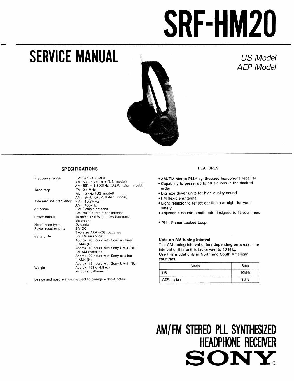
Sony srf hm 20 service manual

This is the 10 pages manual for sony srf hm 20 service manual.
Read or download the pdf for free. If you want to contribute, please mail your pdfs to info@audioservicemanuals.com.

Page: 1 / 10
left right
sony srf hm 20 service manual

Extracted text from sony srf hm 20 service manual (Ocr-read)


Page 1

SRF-HMZO

SERVICE MANUAL

US Model
AEP Model

SPECIFICATIONS

Frequency range FM: 87.5-108 MHz

AM: 5304.710 kHz (US model)

AM: 531 -1,602kHz (AEP, Italian model)
Scan step FM: 0.1 MHz

AM: 10 kHz (US model)

AM: QkHz (AEP. italian model)
intermediate frequency FM: 10.7MHz

AM: 450kHz
Antennas FM: Flexible antenna

AM: Built-in ferrite bar antenna

Power output 15 mW+ 15 mw (at 10% harmonic
distortion)
Headphone type Dynamic

Power requirements 3 V DC
Two size AAA (R03) Dalteries
For FM reception:
Approx. 20 hours with Sony alkaline
AM4 (N)
Approx. 12 hours with Sony UM4 (NU)
For AM reception:
Approx. 30 hours wrth Sony alkaline
AM4 (N)
Approx, 18 hours with Sony UM~4 (NU)
Weight Approx, 193 9 (6,8 oz)
including batteries

Battery lite

Design and specrlications subject to change without notice.

FEATURES

- AM/FM stereo PLL' synthesized headphone receiver

- Capability to preset up to 10 stations In tho doslrod
order

0 Big size driver units for high quality sound

0 FM flexible antenna

0 Light reflector to rellect car lights at night for your
safety

0 Adjustable double headbands designed to lit your head

' PLL: Phase Locked Loop

Note on AM tuning Interval

The AM tuning interval dillers depending on areas The
interval of this unit is factory-set to 10 kHz.

Use thls model only in North and South American
countries.

Model Step
US iOkHz
AEP. Italian QkHz

AM/ FM STEREO PLL SYNlI-IESII
HEADPHONE RECEWER

SONY;

Page 2

SRF- HM20

SECTION 1 This section is extracted from
GENERAL instruction manual.

LOCATION OF CONTROLS

m POWER switch

E] Driver units

El VOL (volume) control

E} Headband
Adjust it to fit your head.

E] FM flexible antenna
Use for FM reception.

E] Light reflector
This reflector reflects car lights at night for your
safety.

Support band
Before putting on the receiver, pull out the support
band fully from the headband. Then adjust it to fit
your head,
When the receiver is not in use, put the support hand
back by pushing down both ends as iilustrated and
push it back underneath the headband.

Battery compartment

[E] ENTER button
Use for storing a station.

@ BAND button
Use for changing AM and FM.

TUNE (tuning) (+ or -) buttons

DX"L0CAL Use for tunging the frequency.

FM SENS [fl] Display window
The indicator displays the frequency and the preset
number.

El MEMORY PRESET (+ or -) buttons
Use for listening to a preset station.

FM SENS (sensitivity) DX/LOCAL selector

Notes on chip component replacement Flexible Circuit Board Repairing
0 Never reuse a disconnected chip component. 0 Keep the temperature of the soldering iron around
0 Notice that the minus side of a tantalum capacitor may 270°C during repairing.

be damaged by heat. 0 Do not touch the soldering iron on the same conductor

of the circuit board (within 3 times).
0 Be careful not to apply force on the conductor when
soldering or unsoldering.