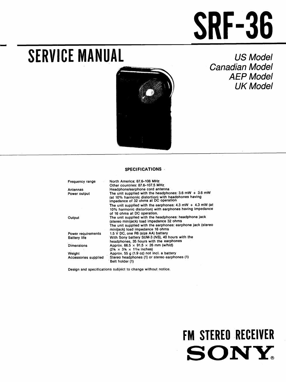
Sony srf 36 service manual

This is the 6 pages manual for sony srf 36 service manual.
Read or download the pdf for free. If you want to contribute, please mail your pdfs to info@audioservicemanuals.com.

Page: 1 / 6
left right
sony srf 36 service manual

Extracted text from sony srf 36 service manual (Ocr-read)


Page 1

SRF-36 a

SERVICE MANUAL USModel

Canadian Model
AEP Model
UK Model

SPECIFICATIONS -
Frequency range North America: 87.6408 MHz
Other countries: 87.8w107.5 MHz
Antennas Headphone/earphone cord antenna 7
Power output The unit supplied wlth the headphones: 36 mW + 36 rnW

tat 10% harmonlc distortion) with headnhones having
impedance at 32 ohms at DC operation
The unit suppllad with the earphones: 4.3 mW + 4.3 MW (at
10% harmonic distortion) with earphones having impedance
of 16 ohms at DC operation.

Output The unit supplied with the headphones: headphone iaok
(stereo mlnijack) load impedance 32 ohms
Yhe unit supplied with the earphones: earphone jack (stereo
minijack) load Impedance 16 ohms

Power requirements 1.5 V DC, one R6 (size AA) battery

Battery Iite With Sony battery SUM-3 (NS), 40 hours with the
headphones, 35 hours with the earphones
Dimensions Approx. 66.5 x 9L5 x 26 mm (wlhld)
(2% x 3% x 1lto Inches)
Weight Approx. 55 9 (19 oz) not incl, 3 battery

Accessories supplied Stereo headphones (1) or stereo earphones (1)
Belt holder (1)

Design and specificatlons subject to change without notice.

FM STEREO RECEIVER
S ON Y2

Page 2

SRF-36

SECTION 1
DISASSEMBLY
KNOB (T) SETTING
0
Turn the shaft of variable _/
capacitor fully in the diree
tion oi arrow. | I o
0 ©
Install knob (T) as 10 \
illustrated ' ,
Shaft of variable
capacitorr
main board
SECTION 2
gunmen ADJUSTMENTS ELECTRICAL ADJUSTMENTS
- Repeat the procedures in each adjustment several ' AbbTEViftiC V
times, and the frequency coverage should be ES:SDan15h model

finally done by the trinuer capacitors.

Adjustment Location: mun mm

- Component Side -
BAND selector: FII
FII SENS selector: DX
VOLUME control: mechanical lid

FM FREQUENCY COVERAGE ADJUSTMENT
Adjust for a min- reading on VTVII.

- on: FM FREQUENCV
US,Canadlan 86. 5|IIIz 109. SM: COVERAGE ADJUSTMENT
AER UK. ES 37.35IIIIZ 108.05Mflz L2: 2nd OSC (57.1mm)

L6 (m ADJUSMTENT
FM MPX ADJUSTMENT (VCO) L4:

FM MPX ADJUSTMENT
1. Connect the frequency counter through lOuF (V00)

electrolytic capacitor between 16! pin 11
and ground.

2. Adjust-tent L4 for the reading of 38kflthUflz
on the frequency counter.

L5: FM FREQUENCY
COVERAGE
2nd 08C (57.1MHz) ADJUSTMENT

Adjust L2 for the reading of 56.75MHzi0.25MHz
on the frequency counter.