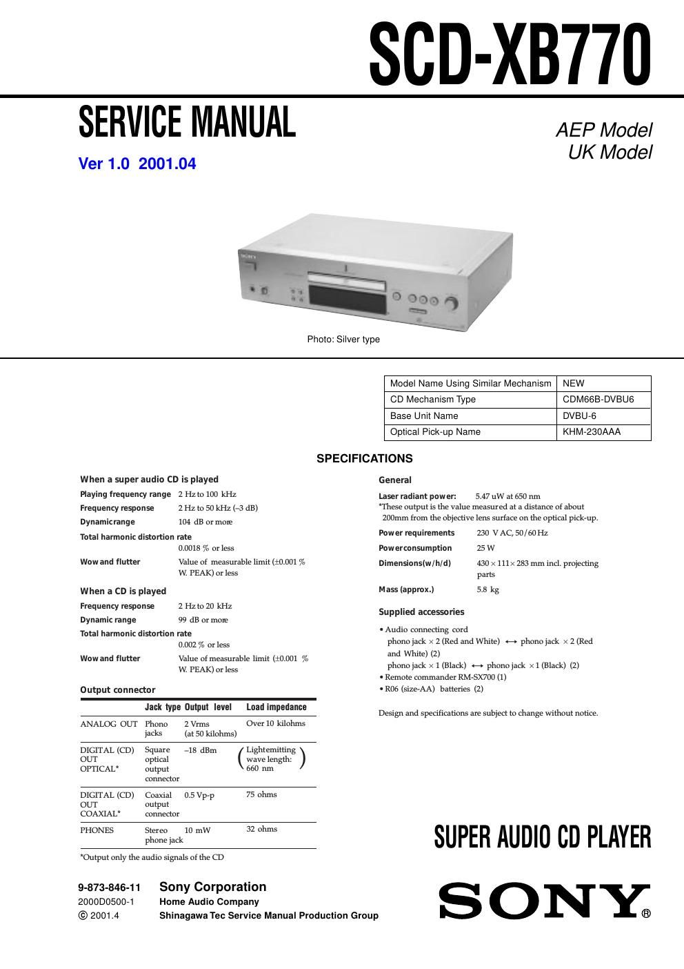
Sony scd xb 770 super audio cd player

This is the 70 pages manual for sony scd xb 770 super audio cd player.
Read or download the pdf for free. If you want to contribute, please mail your pdfs to info@audioservicemanuals.com.

Page: 1 / 70
left right
sony scd xb 770 super audio cd player

Extracted text from sony scd xb 770 super audio cd player (Ocr-read)


Page 2

SCD-XB770

472.
4-3.

4.4.

476.

4-7.
478.
479

4710.
4-11.
4712.

4.14.
4.15.
446.

717. Schematic Diagram 7 POWER/TRANS Boards 7
. IC Pin Function Description ............................

5.

571.
572.
5-3.
5-4.
5-5.

TABLE OF CONTENTS

SERVICING NOTES .. 3
GENERAL .. 5
DISASSEMBLY

Disa. embly Flow .
Cover ..............
Front Panel Section ............
AUDIO Board, MAIN Board ..
Mechanism Deck (CDM66BADVBU6) . .. 10
Base Unit (DVBU~6) ...........................

DIAGRAMS

Notes for Printed Wiring Boards and
Schematic Diagrams .............
Schematic Diagram 7 RF Board
Printed Wiring Boards

7 RF/LOADING Boards 7 .............................................. 15
Printed Wiring Board
7 MAIN Board (Component Side) 7 .............................. 16
Printed Wiring Board
7 MAIN Board (Conductor Side) 7 ................................ l7

Schematic Diagram

7 MAIN (l/5)/ LOADING Boards 7 .......
Schematic Diagram 7 MAIN Board (2/5) 7
Schematic Diagram 7 MAIN Board (3/5) 7
Schematic Diagram 7 MAIN Board (4/5) 7
Schematic Diagram 7 MAIN Board (5/5) 7
Schematic Diagram 7AUDIO/HP Boards 7
Printed Wiring Board

7 AUDIO Board (Component Side) 7 ............................ 24

.. Printed Wiring Boards

7 AUDIO (Conductor Side)/HP Boards 7 ......

Printed Wiring Boards 7 DISPLAY/KEY Board ..
Schematic Diagram 7 DISPLAY/KEY Boards 7 .......... 27
Printed Wiring Boards

7 POWER/TRANS Boards 7 .......................................... 28

EXPLODED VIEWS
Cover Section
Front Panel Section
Chas s Section ................................................
Mechanism Deck Section (CDM66B7DVBU6
Base Unit Section (DVBU-6) ..........................

ELECTRICAL PARTS LIST ............................... 57

Notes on chip component replacement
O Never reuse a disconnected chip component.
O Notice that the minus side of a tantalum capacitor may be damA

aged by heat.

Flexible Circuit Board Repairing
O Keep the temperature of the soldering iron around 270 C durA
ing repairing.

O Do not touch the soldering iron on the same conductor of the

circuit board (within 3 times).
O Be careful not to apply force on the conductor when soldering
or unsoldering.

CAUTION

Use of controls or adjustments or performance of procedures
other than those specified herein may result in hazardous raA
diation exposure.

This appliance is classified as a CLASS 1
LASER product.

The CLASS 1 LASER PRODUCT
MARKING is located on the rear exterior.

CLASSI LASER PRODUCT
LUOKAN I LASERLAITE
KLASS I LASERAPPARAT

The following caution label is located
inside the unit.

I mum um am.

In as Wm IAstiSIHAJNG mm mm
m on mm

was»!

is (I i kEszutEKmL '

SAFETY-RELATED COMPONENT WARNING I!

COMPONENTS IDENTIFIED BY MARK A OR DOTTED
LINE WITH MARK A ON THE SCHEMATIC DIAGRAMS
AND IN THE PARTS LIST ARE CRITICAL TO SAFE
OPERATION. REPLACE THESE COMPONENTS WITH
SONY PARTS WHOSE PART NUMBERS APPEAR AS
SHOWN IN THIS MANUAL OR IN SUPPLEMENTS PUB-
LISHED BY SONY.