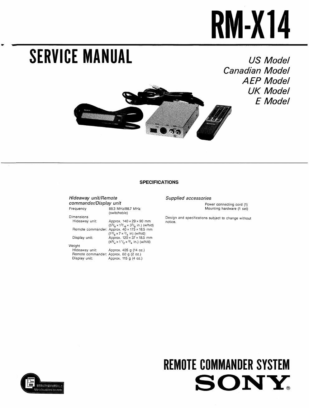
Sony rm x 14 service manual

This is the 21 pages manual for sony rm x 14 service manual.
Read or download the pdf for free. If you want to contribute, please mail your pdfs to info@audioservicemanuals.com.

Page: 1 / 21
left right
sony rm x 14 service manual

Extracted text from sony rm x 14 service manual (Ocr-read)


Page 1

RM-XI4

SERVICE MANUAL us Model

Canadian Model
AEP Model
UK Model
E Model

SPECIFICATIONS
Hideaway unit/Remote Supplied accessories
commander/Display um! Power connecling cord (1)
Frequency 883 MHuseJ MHz Mounnng hardware (1 55)
(swilchable)
Dimensions Design and specihcalvons subject Io change without
Hideaway uniI: Approx. 1A0 x 29 x 80 mm notice.

(55/a x 131 3515 in.) (wlh/d)
Remote commander: Approx 40x175 x185 mm

(15/! x 7 x 3/4 m) (win/d)
Dispxay unit: Approx, 120 x 37 x 18.5 mm

(4% x I '/2 x 3/1 in) (w/hld)

Weigh!
HIdeaway unut: Approx. 405 g (14 oz.)
Remote commander: Approx. 60 g (2 oz.)
Dismay unit: Appwx. 115 g (4 oz.)

REMOTE CUMMANDER SYSTEM

SONY;

Page 2

RM-X14

TABLE OF CONTENTS

Section Title Page
Specifications .................................. 1

1. GENERAL

Location and Function of Controls ----------------- 3
Switches Requiring Initial Settings 4
Installation - - - 5
Connections 5
2. ELECTRICAL ADJUSTMENTS

2-1. DC Balance Adjustment ------------------- 7
2-2 Oscillating Frequency Adjustment ----------- 7

3. DIAGRAMS

3<1. Master Microcomputer

(IC504 ,u PD7SllGGF-F13)

Pin Description .......................... g
3-2. MasterMicrocomputer

(IC503 fl PD750086B-658)

Pin Description .......................... 10
3.3. Block Diagram ........................... 11
3-4. Hideaway Unit Schematic Diagram --------- 13
3-5. Hideaway Unit Printed Wiring Board -------- 15

3-6. Display Unit Printed Wiring Board and
Schematic Diagram - ~ ~ ~

4. EXPLODED VIEWS ------------------- 19

5. ELECTRICAL PARTS LIST ~~~~~~~~~~~~ 21