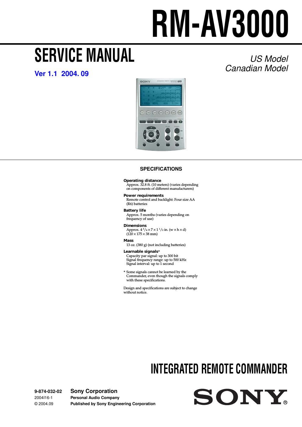
Sony rm av 3000 service manual

This is the 18 pages manual for sony rm av 3000 service manual.
Read or download the pdf for free. If you want to contribute, please mail your pdfs to info@audioservicemanuals.com.

Page: 1 / 18
left right
sony rm av 3000 service manual

Extracted text from sony rm av 3000 service manual (Ocr-read)


Page 1

2 TABLE OF CONTENTS RM-AV3000 1. GENERAL ······································································ 3 2. DISASSEMBLY 2-1. Case (lower) ········································································ 8 2-2. SUB Board ········································································· 8 2-3. MAIN Board and LCD Unit ··············································· 9 3. TEST MODE 3-1. EEPROM Check ······························································· 10 3-2. LCD, All Keys and EL Check ·········································· 10 4. DIAGRAMS 4-1. IC Pin Function ································································ 11 4-2. Printed Wiring Board -“ MAIN Board -“ ··························· 12 4-3. Schematic Diagram -“ MAIN Board -“ ······························ 13 4-4. Printed Wiring Board -“ SUB Board -“ ······························ 14 4-5. Schematic Diagram -“ SUB Board -“ ································· 14 5. EXPLODED VIEWS ·················································· 15 6. ELECTRICAL PARTS LIST ··································· 16 Notes on chip component replacement -Never reuse a disconnected chip component. -Notice that the minus side of a tantalum capacitor may be damaged by heat. Flexible Circuit Board Repairing -Keep the temperature of soldering iron around 270ËšC during repairing. -Do not touch the soldering iron on the same conductor of the circuit board (within 3 times). -Be careful not to apply force on the conductor when soldering or unsoldering.

Page 2

3 RM-AV3000 SECTION 1 GENERAL This section is extracted from instruction manual. Location and Function of Controls 1Clock Display key (page 8) Displays the clock, the transmission mark, the battery mark and the timer mark. 2Mode Display key (page 8, 13, 20, 30, 32, 40) Displays the status of the selected mode. Function of the key changes according to the selected mode. 3LCD touch key display The keys used for operating each component and setting the Commander are displayed. NoteDo not press the touch keys using sharp objects such as pins or ball-point pens. MENU EXIT COMMANDER OFF MORE 3 2 1 TV STB VCR DVD CD AMP OTHER TIMER LIGHT MUTING RECALL CHANNEL VOLUME SYSTEM CONTROL OK 2 1 5 7 qk qh qg qj8 9 q; 3 4 6 qa qs qd qf 4Label keys (page 8, 13, 20, 23, 30, 32, 40, 79) The selected modes (up to 8 characters in each Label key) are displayed. Labels change in the order from the first stage to the third stage and come back to the first, and so on, each time you press the Mode Display key, OTHER, MORE, or TIMER button according to the selected mode. 5Component Select buttons (page 12) Selects the component to control. 6OTHER button (page 13) Label keys change in the order from the first stage to the third stage and come back to the first, and so on, each time you press the OTHER button when the selected component name is displayed on the Label keys. 7TIMER button (page 68) Used to set the timer program, and to set the timer program on or off. 8LIGHT button (page 76) Used to light up the LCD display in the dark. Press the button once to turn on the light, and once again to turn it off. 9 COMMANDER OFF button Turns the power of the Commander off. Then all the display contents are turned off. q; CHANNEL +/-“ buttons (page 88, 89, 90, 91) Select the channel. qa RECALL button (page 88) qs VOLUME +/-“ buttons* (page 19, 29) Adjust the volume. qd MUTING button* (page 19, 31) Mutes the audio. Press the button once again to resume at the previous volume. Getting Started 6