Sony rm 30 service manual

This is the 4 pages manual for sony rm 30 service manual.
Read or download the pdf for free. If you want to contribute, please mail your pdfs to info@audioservicemanuals.com.

Page: 1 / 4
left right
sony rm 30 service manual

Extracted text from sony rm 30 service manual (Ocr-read)


Page 1

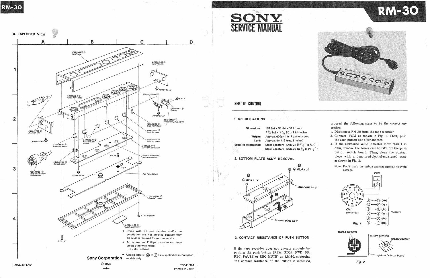
8. EXPLODED VIEW

A

2235514420 (3)
Panel m, std:

PTPWH 2.6x 6%

Cord, mum comm!
(w/conmrwl

9-954-451-12

X-22366W0 (D
Panel Aw

)9:wa ®
Hold Auy, knob

354-91552] ®
Knob IA), rewind

221753141 ®
CMECL mum

FTPWH 2.6 x 6

52.531 10 0

Sony Corporation

© 1976
_4_

1d?

D

Bzex 10

27236-619470 (3
Label, muff/cation

Items with no

- Mm Any, mum

2236-61500 (E)
Pm! 7R), lrde

éPTTM/HZJXS

Bracket, microswmh

52x8 7 . j j 7 Q
/ si e I V
2a3sazooa® N
Cushion
. PWWHZEX6 '

1515544470 (E
M/cmxwitch, arc MUTE

zen-5mm ® is"
Knob, REC MUTE

354875541 ®
Knob/ELM
\ 3548776501 (E
Knob/Chum
3548v755i1®
Knob (AI, Immm

hinted Circuit Board,
push button Mlmh

X-2236-6M0 ©
Case As'y, law

new

part number and/or no

description are not stocked because they
are seldom required for routine service.

All screws are Phillips (cross recess) type
unless otherwise noted.

(-l = slotted head

Circled letters (@ to® ) are applicable to European

models only

70041 58-1
Printed in Japan

SONm

m

REMflTE CGNTROL

1. SPECIFICATIONS

Dimensions: 188 (w) x 33 (hl x 50 (Cl) mm
7745 (w) x I 5/la (b) x2 (d) inches
Weight: Approx. 6309 (1 lb 7 02) with card
Card: Approx. 4m (13 feet, 2 inches)
Supplied Accessories: Stand adaptor: SAD-24 (PFl/Z I to Ul/4 ')
Stand adaptor: SAD-25 (u 54m PF '4 'l

2. BOTTOM PLATE ASS'Y REMOVAL
9

(.9 32.6): 10


(43 52.5 x 10

lower case ass'y

3. CONTACT RESISTANCE OF PUSH BUTTON -

If the tape recorder does not operate properly by'
pushing the push button (REW, STOP, FWD, FF,
REC, PAUSE or REC MUTE) on RM-30, supposing
the contact resistance of the button is increased,

proceed the following steps to be the correct op-

eration.

1. Disconnect RM-30 from the tape recorder.

2, Connect VOM as shown in Fig. 1. Then, push
the each button one after another.

3. If the resistance value indicates more than 1 k:

ohm, remove the lower case to take off the push
button switch board. Then, clean the contact
piece with a denatured-alcohol-moistened swab
as shown in Fig. 2.

Note: Dont scrub the carbon granules strongly to avoid
damage.

VOM


® ~® l»)

-@ (0)
cm (D ._.® 0)
connector (D H. (I ) measure

®~© (0
Fig. 7 ©-~® (In)

carbon granules

carbon granules
rubber cantsct

printed circuit board

F (g. 2

Page 2

RM-3O

4. CIRCUIT DESCRIPTIOg

When connecting RM-30 to the tape recorder, the
push buttons except REC MUTE button are connect»
ed in parallel with the operation button on the tape
recorder. Thus, the tape recorder is operated by
the each push button on RM-30 as same as the tape
recorder function button,


REC MUTE Operation (In the case that RM-30 is

connected to EL-7.)

1. When pushing REC MUTE button, Q746 turned
on. (route @ )

2. Q501 turned off, so Q306 and Q307 turned on.
(route a )

3. As the result, the recording signal is muted.


RM-30 _
(- o « I > » n W
U -
I «£0 'J-k- 'fl-o £1 '£- '% / w
. T I I II I T I I f 9" I
EL-7 (EXAMPLE) 0308.309 v | I I
V RECORD AMP I a | |
[>1
REMOTE
40 com I I
0306,30? CONNE 0R 3 I
RECORD RECORD
SIGNAL MUTING g I
:9 0501.745 (49 I i I
more 31 I I 'e
0306 0307 r - _ I _ : ~J.
I Ll g I ____________JI I
| el @l | ,
I I I I
k- _ _ L_ - _ _ .1 n :
I v
R-CH I
(0406.407) JI
(- - -
l 1/

Fig. 3

5. SCHEMATIC DIAGRAM

FAST
REWIND STOP FORWARD FORWARD RECORD PAUSE
44 I V » 0 II

a: db .5 r4:- :1:- dL-n .5'
T087 T56 T85 T054 955 T$2 ONT

I4

DI

SI

6. MOUNTING DIAGRAM
- Conductor Side -
v OFF

meal


mu '

mam

C NI CONNECTOR
/-

uwt

a an
I F
S7 56 SS
REWIND STOP FORWARD

7. ELECTRICAL PARTS LIST

Ref. No. Part No. Description
SEMICONDUCTOR
D1 ® 1T40

MISCELLANEOUS

51 1-516-544-00 ® Microswitch, REC MUTE
1551-23200 ® Cord, remote control (w/ Connector)

_3_

ACCESSORIES AND PACKING MATERIALS

Part No.

2-100-961-00
2-236-617-00
2-521-203-00
3-701-628-00
3-770-034-11

Description

Adaptor, stand; SAD-24
® Carton

© Adaptor, stand; SAD-25
® Bag, plastic

® Manual, instruction

o circled letters (® to® ) are appIicabIe to European
models only