Sony ps x 6 service manual

This is the 20 pages manual for sony ps x 6 service manual.
Read or download the pdf for free. If you want to contribute, please mail your pdfs to info@audioservicemanuals.com.

Page: 1 / 20
left right
sony ps x 6 service manual

Extracted text from sony ps x 6 service manual (Ocr-read)


Page 1

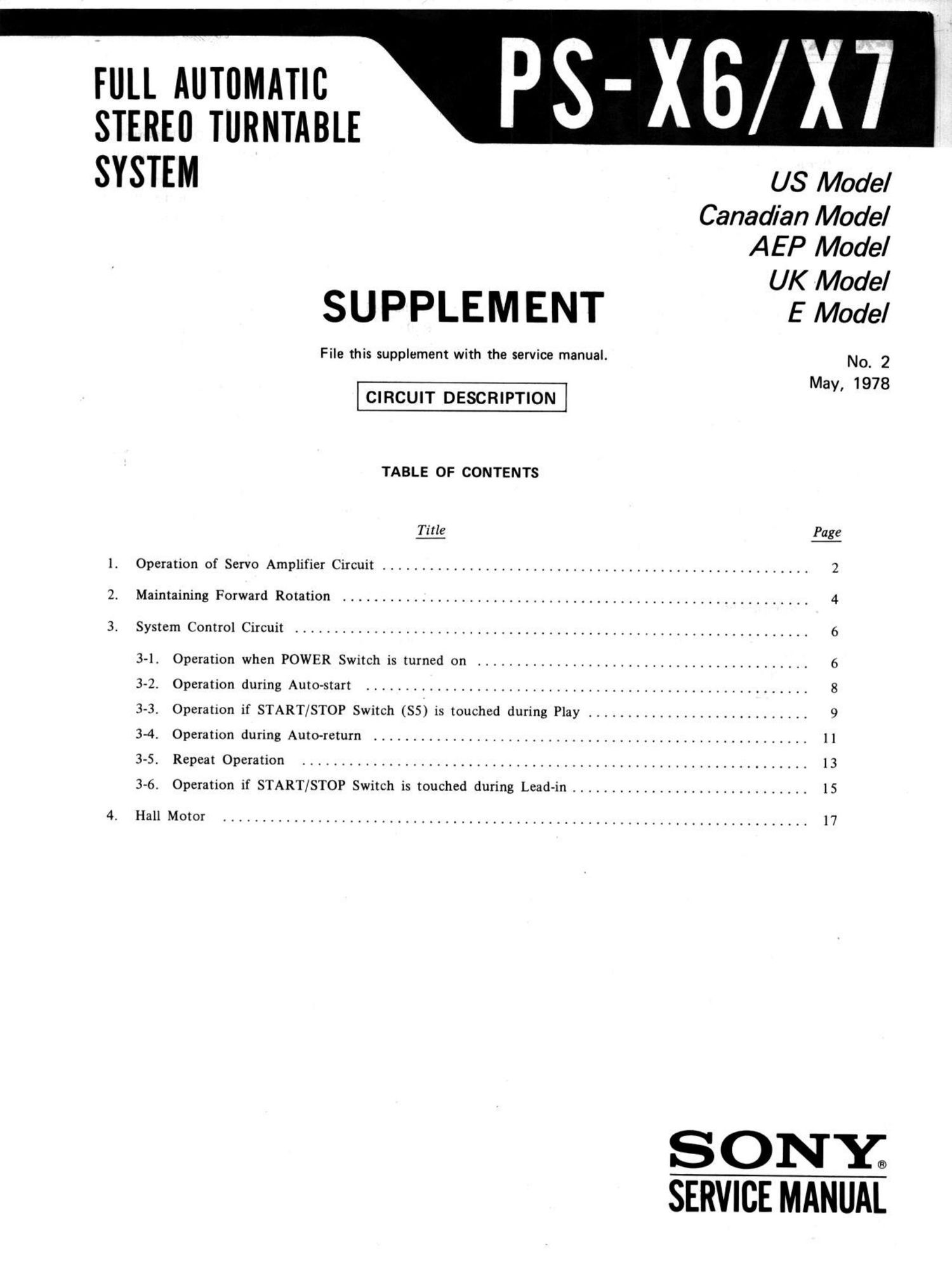
FULL AUTOMATIC
STEREII TURNTABLE

SYSTEM

SUPPLEMENT

File this supplement with the service manual.

CIRCUIT DESCRIPTION

TABLE OF CONTENTS

Title

I. Operation of Servo Amplifier Circuit ................................

2. Maintaining Forward Rotation
3. System Control Circuit

3-1. Operation when POWER Switch is turned on

3-2. Operation during Auto-start

3-4. Operation during Auto-return

3-5. Repeat Operation

3-6. Operation if START/STOP Switch is touched during Lead-in ........

.....................................

3-3. Operation if START/STOP Switch (SS) is touched during Play ......

..........................................

....................................................

US Model
Canadian Model
A E P Model

UK Model

E Model

No. 2
May, 1978

Page

...................... 2

...................... 9

S ON Y;
SERVICE MANUAL

Page 2

_Ps-X67X7 |

1. Operation of Servo Amplifier Circuit (See Fig. 1-1)
During Motor Start

1.

When the power switch is turned on, 0202 is
still turned off since an output signal from the
MG head is not applied to [Cl-2. C204 will
thus charge up through R210, R209 and RV201
(or R208 and RV201 for 45 rpm).

Once the emitter voltage of 0203 (charging
voltage applied to the base of 0203) exceeds
+VBE, this transistor turns on.

0205 is thus turned on, thereby applying a
voltage to [Cl-1.

Limiter Circuit

I.

Once the turntable starts to rotate, an output
signal is produced by the MG head.

Although the MG head output signal is a sine
wave, there is some fluctuation in amplitude.
Therefore, above a certain level, this sine wave

This limiter circuit (ICl-2, 0201) serves to
prevent incorrect detection of amplitude fluct-
uations as frequency changes.

The square wave signal on the collector of 0201
is then applied to the phase control circuit.

Differential Circuit

The square wave signal on the collector of 0201
is changed to a triangular wave by C203, R206 and

R207.

The differentiated (triangular) pulse triggers

the sawtooth wave generator transistor (0202).

Sawtooth Wave Generator Circuit

1.

While 0202 is turned off, C204 is charged up
through R210, R209 and RV201 (or R208 and
RV201 for 45 rpm). But when the positive part
of the differentiated wave turns 0202 on,
C204 discharges immediately, resulting in the
collector voltage of 0202 dropping to 0V.

is changed into a constant-amplitude square 2. After the 9 portion of this differentiated wave
wave. has passed on, 0202 is again turned off, and
C204 is charged up, resulting in the 0203 base
voltage forming a sawtooth wave signal.
Waveform Rectification
1. The [Cl-2 output signal is amplified by 0201 Comparator

to obtain a complete square wave signal. The
D201 is employed to maintain the base voltage
of 0201 at $0.6Vp-p.

l. The sawtooth wave signal is applied to the
comparator circuit formed by 0203 and 0204.
The base of 0204 is biased by the reference
voltage produced by voltage division of 8+ by
the output from R213, R214, R215 and the
phase control circuit.


8* 52-2
Jlflll 33* mm-
! mnmlcv'muir
to mind No. :5 or R209 R208 02a:
":2!le cmtmll R20 280633? 9 $23577 gig
0202 V
l :23; mm mam W W" " W s+
9 (umoorh mu 205
WM) mam) C203 "20' R211 RZI3
rcr-2 mute f]
MGH limiter amp 0 lCI-Z 0201 R206 0203 w
MGM 0 7 \ O. h J
:mglmw £20, 1.. R214 L":%"'"""'
" R203 20' R207 "C204 92'?
"20' HF
0207 R215
1cm ITO

reference voltage

Fig. 1-1.