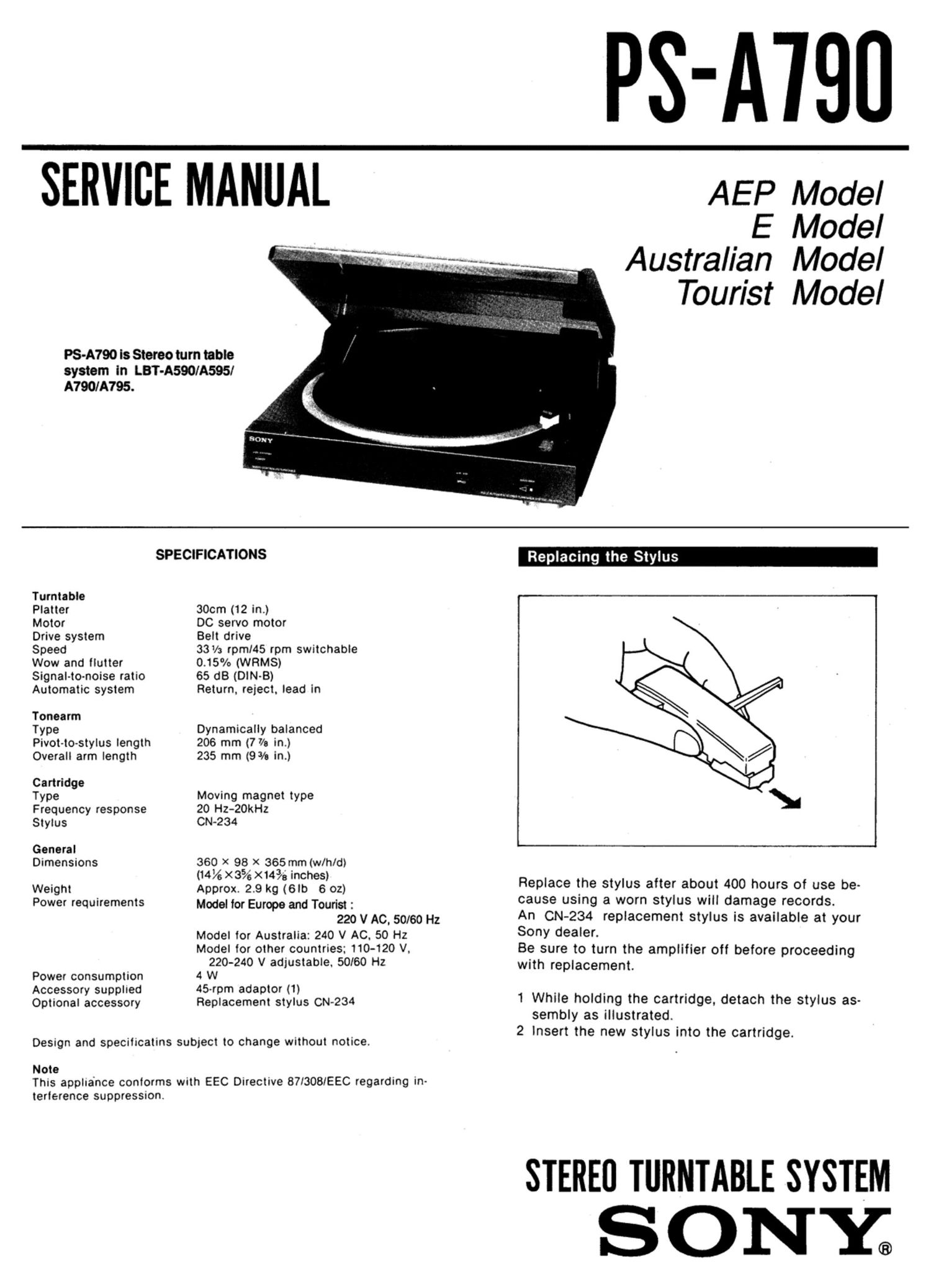
Sony ps a 790

This is the 8 pages manual for sony ps a 790.
Read or download the pdf for free. If you want to contribute, please mail your pdfs to info@audioservicemanuals.com.

Page: 1 / 8
left right
sony ps a 790

Extracted text from sony ps a 790 (Ocr-read)


Page 1

SERVICE MANUAL

PS-A790 is Stereo turn table
system in LBT-A590/A595/

PS-ATBU

AEP Model
E Model

Australian Model

Tourist Model

A790/A795.
SPECIFICATIONS
Turntabie
Platter 30cm (12 in.)
Motor DC servo motor
Drive system Belt drive
Speed 331/; rpm/45 rpm switchable

Wow and flutter
Signal-to-noise ratio
Automatic system

Tonearm

Type

Pivot-to-stylus length
Overall arm length

Cartridge

Type

Frequency response
Stylus

General
Dimensions

Weight
Power requirements

Power consumption
Accessory supplied
Optional accessory

0.15% (WRMS)
65 dB (DIN-B)
Return, reject, lead in

Dynamically balanced
206 mm (7 7/3 in.)
235 mm (9 3/3 in.)

Moving magnet type
20 H2-20kHz
CN-234

360 X 98 X 365 mm (wlh/d)
(14% x3% X1193 inches)
Approx. 2.9 kg (6th 6 02)
Model for Europe and Tourist :

220 V AC. 50160 Hz

Model for Australia: 240 V AC. 50 Hz

Model for other countries; 110-120 V,

220-240 V adjustable. 50/60 Hz
4 W
45-rpm adaptor (1)
Replacement stylus CN-234

Design and specificatins subject to change withOut notice.

Note

This appliance conforms with EEC Directive 871308lEEC regarding in-

terference suppression.

Replace the stylus after about 400 hours of use be-
cause using a worn stylus will damage records.

An CN-234 replacement stylus is available at your
Sony dealer.

Be sure to turn the amplifier off before proceeding
with replacement.

1 While holding the cartridge, detach the stylus as-

sembly as illustrated.
2 Insert the new stylus into the cartridge.

STEREI] TURNTABLE SYSTEM

ONYi

Page 2

Connections

__ -_-_J

turntable

Amplifier

@

.-.- w a: mew rum-mvratm- ms :uy'I-r-

For the customers of the model equipped with the
voltage selector (Fig. fl)

Check that the voltage selector located under the
turntable is set to the local power line voltage. It not.
set the selector to the correct position belore con-
necting AC power cord to a wall outlet.

To install the turntable (Fig. B)

Gripping the three holes at the center of the turnta-
ble with your right hand. pull the black rubber belt On
to the pulley with y0ur Ieit thumb. Set the turntable
on the spindle. and hook the belt on the pulley. To
make Sure it operates properly, spin the turntable
once or twice in the clockwise direction with your

hand.

Location of Controls

Connections (Fig. )
COnnect the red plug to the right-channel jack (R).
and the white plug to the lelt-channel iack (L).

To remove the dust cover (Fig. E)
Open the cover fully and pull it up.

Notes on installation

. Place the turntable on a level surtace. .

- Avoid placing the unit near electrical appliances (such as
a televiswn. hair dryer. or lluorescent lamp) which may
cause hum or noise.

- Place the turntable where it will not be subgect to any
vibration. such as lrom speakers. slamming ot doors. etc.

- Keep the unit away lrom direct sunlight. extremes o! tem-
perature. and excessnve dust and morslure.

my

y.~'.....- I,» _ a.
45-rpm-adaplor-\

POWER switch

START [STOP button

Tonearm

Drop pornl adIustment hole

Cueing lever

Cartrige

i gt-7'4: 2151333 .L rm: Mm: 2'" may" mur'r'at it»? 71-.

..__2_