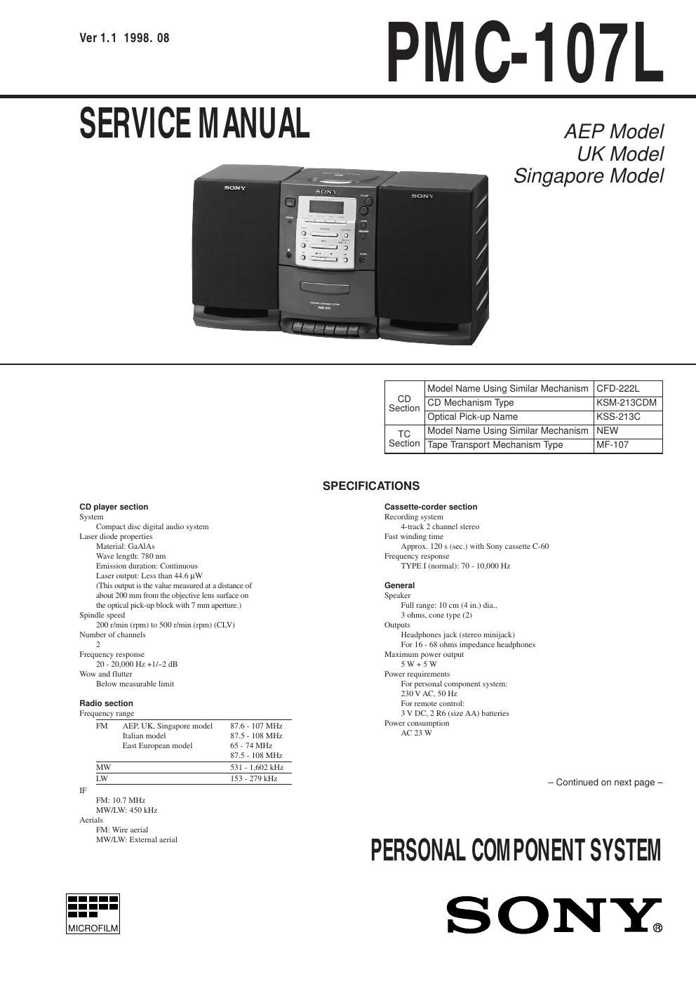
Sony pmc 107 l service manual

This is the 8 pages manual for sony pmc 107 l service manual.
Read or download the pdf for free. If you want to contribute, please mail your pdfs to info@audioservicemanuals.com.

Page: 1 / 8
left right
sony pmc 107 l service manual

Extracted text from sony pmc 107 l service manual (Ocr-read)


Page 1

Ver1.1 1998. 08

PMC-107L

SERVICE MANUAL

AEP Model
UK Model
Singapore Model

co player section
System
Compact disc digital audio system
Laser diode properties
Material: GaAIAs
Wave length: 780 um
Emission duration: Continuous
Laser output: Less than 44o pw
(This output is the value measured at a distance of
about 200 mm from the objective lens surface on
the optical picieup block with 7 mm aperture.)
Spindle speed
200 r/niin (rpm) to 500 t'lnun (rpm) (CLV)
Number of channels
2
Frequency response
20 , 20000 Hz +1er dB
Wow and flutter
Below measurable limit

Radio section
Frequency range

FM AER UK, Singapore model 87.6 , 107 MHZ

llalian model 87.5 , 108 MHZ
East European model 65 , 74 MHZ
87.5 , 108 MHZ
MW 531 , 1.602 kHZ
LW [53 , 279 kHz
IF
M: 10.7 MHZ
MW/LW: 450 kHz
Aerials
FM: Wire aerial

MW/LW: External aerial

.-
MICROFILM

Model Name Using Similar Mechanism CFD-222L

CD Mechanism Type KSM-2130DM

Optical Pick-up Name KSS-213C
TC Model Name Using Similar Mechanism NEW

Section Tape Transport Mechanism Type MF-107

CD
Section

SPECIFICATIONS

Cassette-comer section
Recording system
detrack 2 Channel stereo
Fast winding time
Approx. 120 s (Sec) with Sony cassette C760
Frequency response
TYPE I (normal): 70 , 10.000 HZ

General
Speaker
Full range: 10 cm (4 in.) dia,.
3 ohms cone type (2)
Outputs
Heudphones jack (stereo intnijack)
For 16 . 58 ohms impedance headphones
Maximum power output
5 W + 5 W
Power requirements
For personal component system:
230 V AC. 50 HZ
For remote control:
3 V DC, 2 Ro (size AA) batteries
Pow er consumption
AC 23 W

- Continued on next page -

PERSONAL COMPONENT SYSTEM

SONY;

Page 2

5-6. SCHEMATIC DIAGRAM - CD SECTION - - Refer to page 42 for IC Block Diagrams.

PMC-107L

cuIms
ICD BOARD]
5m, cumz
up_
A [a mum WI
0 XLAT
ELUK
H737 IIIK XRST
_ o sens
u7ui 7u2 ° 75 EUNTRDL
I Lu FEVER R" '" SEEK $37002
CENTRE. 0 SD50
B 0 scan
was I- LuuN
HIIi [:95 WE an um 5" _:> noon
I lDV I ms i-<
5" R1 -| £737 farm
.9 M1 if": it
zsmsus ms .5. me man.
A OPT I C-AL P I CK -UP I um 51%
I W :73; n n. I
C BLOCK (KSS- 2130) -
I :10] am
" E vcc cm in say m2 "fill a a 5 cm ban»
I (-< m a,
a n v: ms mm ..
u 1 w m cm
*Q-IP 'f' _ 11p '- 0M) t a. mv
x A 2.8 I
- 0- WHY A8! 2.5 I C702
D . e a a? . was at 1 2.5
I was at =75: H733 W 3.3. mm
'1 D O- wtqgau I" 703 [752 Ml
. o_@ 533}. lax .-
8 I) :1 am am
- a F o__ my 2 AI TRAVERSE I I
/ WIS A t h [7
I La I 6 *6 I I -5 mum.
RWDZ 2.2! 782 £730
._@_I_?J 2 5 Vi: Co a: a sverH XU m.
E M 0_ I sznvo FRUEESSDR
vb ] was m | W [m 2.5 R173" I
TRACKING 2.5
o- ._II_.
ID-ILRIEKINGISI GAIN v x 2.5 my link 3.7%? Z5. 7?
R7l£ R7l5 E7ll fl.fl22 Z 5
- I m. >-I 4H >-ui i
Focus 2-5 cm. cm
EDIL Em am 25 man. u.m
_ a link
ms I
my
F H W
I E7I3 LEW: I
E712
ms zznnp um um « Inn» ,_I
_ I- UM
ms min I
a.
R7Zl m H
mm s cm
I : 0.1111
R a.
G ». .7 .7523 my 5 m 1., mt 1.75,
= . éai . is: m u. Ifiwn III:
5 cm ms a d
I"; "MT £739 I 11° W = g s. me am me 577% 5727] I
. , 3 an: m .1 s mun: lax fi_II_
I tum E I: E J. (Nggm
K x A
I inIInn :75 "V "-5
- . B
-| m7 5"
'I' a) L.CH
CD MOTOR x x I: MAIN
H ma cm , , ; MM: some
("I 2772 mm .-zzu luv a 58 a a N 5v (2/2)
BOARD rm 21 T A 7 In»: E E R ENPSN
>-i HH I K 5 5"
(SPI7NDLEI I "7 E P GNU
_ Em mm am g [ml cm.
III- P " AIYnizz m 3 man- man. I
M70! R7 1.
IISLEDIILZWI 33. >-u-<
I763 E755
I zzx innnn
DWES-I 1:711} 'I'
BASSSDFF 37575
am: A smug siy '
METER DRIVE 373? T
- - H7 [75! R757 I
m many n m]
[7&5 A I C704 WWI
5 9-1 ' ' 2m luv "V U/A couvgmgn
J I LI 1 4 7 m w ill: I
. . . v
{#7 Riki. T Fungal: 517 TR: 11-225 in ,W
m _ _ _ _ _ _ _ _ _ _ _ _ _ _ _ _ _ _ _ I
Note:
- All capacitors are in uF unless otherwise noted. pF: uuF - . . - Waveforms are taken with a oscilloscope.
50 WV or less are not indicated except for electrolytics - E adjustment for repair. Voltage variations may be noted due to normal produc-

and tantalums.
- All resistors are in Q and I/AW or less unless otherwise

specified. no mark :CD STOP

Note: The components identified by markA or dotted line
with mark A are critical for safety.
Replace only with part number specified.

tion tolerances.

_29_

- Voltage and waveforms are do with respect to ground
under no-signal conditions.

- Voltages are taken with aVOM (Input impedance 10 M9).
Voltage variations may be noted due to normal produc-

tion tolerances.
- Circled numbers refer to waveforms.
- Signal path.

a : CD

_30_