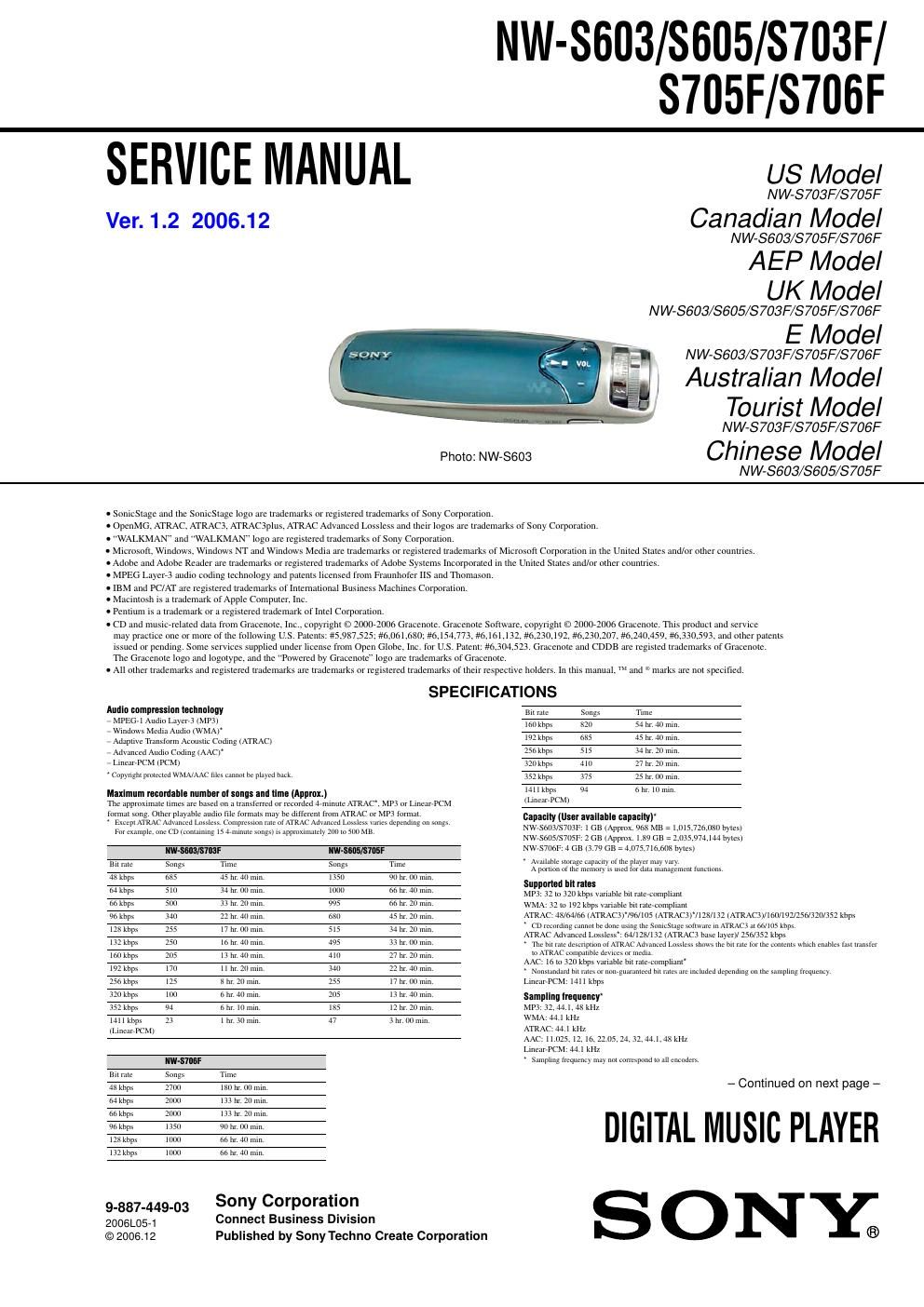
Sony nw s 603 service manual

This is the 49 pages manual for sony nw s 603 service manual.
Read or download the pdf for free. If you want to contribute, please mail your pdfs to info@audioservicemanuals.com.

Page: 1 / 49
left right
sony nw s 603 service manual

Extracted text from sony nw s 603 service manual (Ocr-read)


Page 1

2 NW-S603/S605/S703F/S705F/S706F TABLE OF CONTENTS 1. SERVICING NOTES ............................................... 3 2. GENERAL ................................................................... 5 3. DISASSEMBLY 3-1. Disassembly Flow ........................................................... 6 3-2. Cover (Rear) Assy ........................................................... 7 3-3. Window ........................................................................\ ... 7 3-4. Button (3D) Assy ............................................................. 8 3-5. Holder (Rear) ................................................................... 8 3-6. MAIN Board Scetion ....................................................... 9 3-7. Lithium Ion Battery, MAIN Board .................................. 9 3-8. OLED Sub Assy .............................................................. 10 3-9. SWITCH Board ............................................................... 10 3-10. Knob (Jog) ....................................................................... 11 3-11. Headphone Assy .............................................................. 12 4. TEST MODE .............................................................. 13 5. DIAGRAMS 5-1. Block Diagram ................................................................ 14 5-2. Printed Wiring Board -“ MAIN Board (Side A) -“ ............ 16 5-3. Printed Wiring Board -“ MAIN Board (Side B) -“ ............ 17 5-4. Schematic Diagram -“ MAIN Board (1/7) -“ .................... 18 5-5. Schematic Diagram -“ MAIN Board (2/7) -“ .................... 19 5-6. Schematic Diagram -“ MAIN Board (3/7) -“ .................... 20 5-7. Schematic Diagram -“ MAIN Board (4/7) -“ .................... 21 5-8. Schematic Diagram -“ MAIN Board (5/7) -“ .................... 22 5-9. Schematic Diagram -“ MAIN Board (6/7) -“ .................... 23 5-10. Schematic Diagram -“ MAIN Board (7/7) -“ .................... 24 5-11. Printed Wiring Board -“ SUB Board -“ ............................. 25 5-12. Schematic Diagram -“ SUB Board -“ ................................ 25 5-13. Printed Wiring Board -“ SWITCH Board (Side A) -“ ....... 26 5-14. Printed Wiring Board -“ SWITCH Board (Side B) -“ ....... 27 5-15. Schematic Diagram -“ SWITCH Board -“ ........................ 28 6. EXPLODED VIEWS 6-1. Cover (Rear) Assy Section (NW-S603/S605) ................. 38 6-2. Cover (Rear) Assy Section (NW-S703F/S705F/S706F) ............................................. 39 6-3. Window Section .............................................................. 40 6-4. MAIN Board Section ....................................................... 41 6-5. SWITCH Board Section .................................................. 42 6-6. Frame Scetion .................................................................. 43 7. ELECTRICAL PARTS LIST ................................ 44 Notes on chip component replacement - Never reuse a disconnected chip component. - Notice that the minus side of a tantalum capacitor may be damaged by heat. Flexible Circuit Board Repairing - Keep the temperature of the soldering iron around 270 ˚C during repairing. - Do not touch the soldering iron on the same conductor of the circuit board (within 3 times). - Be careful not to apply force on the conductor when soldering or unsoldering. Fr equency response20 to 20,000 Hz (single signal measurement) FM Fr equency range (NW-S703F/S705F/S706F only)87.5 to 108.0 MHz IF (FM)375 kHz AntennaHeadphon e cord antenna InterfaceHeadphone: Stereo mini WM-PORT (multiple connecting terminal): 22 pin H i-Speed USB (USB 2.0 compliant) Operating temperature5Β°C to 35 Β°C (67 Β°F to 95 Β°F) Power source Bu ilt-in rechargeable lithium-ion battery USB power (from a computer through supplied USB cable) Battery life (continuous playback) **This is when the power save setting is Save ON Super, and Equalizer, VPT ,Clear Stereo , or Dynamic Normalizer is set to OFF. The battery duration will vary depending on temperature and usage. NW-S603/S605 Playback at ATRAC 132 kbps Approximately 48 hours Playback at ATRAC 128 kbps Approximately 44 hours Playback at ATRAC 48 kbps Approximately 46 hours Playback at ATRAC Advanced Lo ssl ess 64 kbps Ap p r o x im at el y 33 hours Playback at MP3 128 kbps Approximately 44 hours Playback at WMA 128 kbps Approximately 39 hours Playback at AAC 128 kbps Approximately 45 hours Playback at Linear-PCM 1411 kbps Approximately 42 hours At r e co r d i n g Ap p r o ximately 10 hours NW-S703F/S705F/S706FWith Noise Can celin g fu n ct ion ONWith Noise Can celin g fu n ct ion OFF Playback at ATRAC 132 kbps Approximately 44 hours Approximately 50 hours Playback at ATRAC 128 kbps Approximately 41 hours Approximately 46 hours Playback at ATRAC 48 kbps Approximately 43 hours Approximately 48 hours Playback at ATRAC Advanced Lo ssl ess 64 kbps Ap p r o x im at el y 28 hours Approximately 35 hours Playback at MP3 128 kbps Approximately 41 hours Approximately 46 hours Playback at WMA 128 kbps Approximately 37 hours Approximately 41 hours Playback at AAC 128 kbps Approximately 42 hours Approximately 47 hours Playback at Linear-PCM 1411 kbps Approximately 39 hours Approximately 44 hours At r e c ei vi n g FM broadcasting Approximately 19 hours Approximately 20 hours At r e co r d i n g Ap p r o x im at el y 10 hours Dimension (w/h/d) (w/h/d, projecting parts not included) 87.2 Γ— 27.4 Γ— 14.9 mm (3.4 Γ— 0.9 Γ— 0.6 inches) Mass Supplide AccessoriesApprox. 47 g (Approx. 2 oz) Please check the accessories in the package. Headph ones (1) Headphon e extension cord (1) Ea rbuds (Size S, L) (1) USB cable (1) Attachme nt (1) Us e when connecting the player to the optional cradle (BCR-NWU3) * 1, etc. CD-ROM * 2 (1) Quick Start Guide (1) - SonicStage software - Operation Guide (PDF file) *1Av a i l a b le soon. Depen ding on the country/region in which you have purchased the pl ay er, some optional accessories may not be available. *2Do not attempt to play this CD-ROM in an audio CD player. Design and specifications are subject to change without notice. US and foreign patents licensed from Dolby Laboratories. CAUTION Danger of explosion if battery is incorrectly replaced. Replace only with the same or equivalent type.

Page 2

3 NW-S603/S605/S703F/S705F/S706F NOTE THE IC201, IC2701, IC3005 AND IC3007 ON THE MAIN BOARD REPLACING Replacement of IC201, IC2701, IC3005 and IC3007 on the MAIN board used in this set requires a special tool NOTE THE IC101, IC401 AND IC3001 ON THE MAIN BOARD REPLACING When IC101, IC401 and IC3001 on the MAIN board is damaged, exchange the new MAIN board for the MAIN board which IC damaged NOTE THE IC1301 ON THE SUB BOARD REPLACING When IC1301 on the SUB board is damaged, exchange the new SUB board for the SUB board (included in MAIN board) which IC damaged SECTION 1 SERVICING NOTES NOTE THE MAIN BOARD REPLACING When the MAIN board is replaced, format it according to the following. UNLEADED SOLDER Boards requiring use of unleaded solder are printed with the lead- free mark (LF) indicating the solder contains no lead. (Caution: Some printed circuit boards may not come printed with the lead free mark due to their particular size) : LEAD FREE MARK Unleaded solder has the following characteristics. - Unleaded solder melts at a temperature about 40 ˚C higher than ordinary solder. Ordinary soldering irons can be used but the iron tip has to be applied to the solder joint for a slightly longer time. Soldering irons using a temperature regulator should be set to about 350 ˚C. Caution: The printed pattern (copper foil) may peel away if the heated tip is applied for too long, so be careful! - Strong viscosity Unleaded solder is more viscou-s (sticky, less prone to flow) than ordinary solder so use caution not to let solder bridges occur such as on IC pins, etc. - Usable with ordinary solder It is best to use only unleaded solder but unleaded solder may also be added to ordinary solder. Minimum System Requirements (for the player) - Computer IBM PC/AT orcompatible computer preinstalled wi th the following Windows operating systems: -“ Windows 2000 Professional (Service Pack 3 or later) -“ Windows XP Home Edition -“ Windows XP Professional -“ Windows XP Media Center Edition -“ Windows XP Media Center Edition 2004 -“ Windows XP Media Center Edition 2005 Not suppor ted by OSs other than above. - CPU: Pentium III 450 MHz orhigher - RAM: 128MB or more - Ha rd Disk drive: 200MB or more of availa ble space (1.5GB or more is recommended) More spac e may be required, depending on the version of the operating system. Additional space is req uired for storing music data. - Display: -“ Screen Resolution: 800 Γ— 600 pixels (or higher) (recommended 1,024 Γ— 768 or higher) -“ Colors: High Color (16bit) (or higher) (SonicStage may not operate properly at color settings at or below 256 colors.) - CD-ROM drive (supporting Digital Music CD play back capabilities using WDM) To create original CDs or to back up audio CDs, a CD-R/RW drive is required. - Sound board - USB port (Hi-Speed USB is recommended) - Internet Explorer 5.5 or later needs to be installed. - Internet connection is required to use the CD Data Base (CDDB) or Electronic Music Distribution (EMD). We do not guarantee operation for all computers even if they meet the above System Requirements. Not support ed by the following environments: -“ Personally constructed computers or operating systems -“ An environment that is an upgrade of th e original manufacturer-installed operating system -“ Multi-boot environment -“ Multi-monitor environment -“ Macintosh Formatting Memory (Format) If the memory is formatted, all music data, other stored data and registered jacket pictures will be erased. Be sure to verify the data stored in memory prior to formatting and export any necessary data to SonicStage or the hard disk of your computer. Yo u can format the bu ilt-in flash memory of the player. to button DISPLAY/HOME button to Shuttle switch Note Pr ess and hold the DISPLAY/HOME button in the stop mode until the HOME screen appears. Rotate the shuttle switch to select butt on to confirm. butt on to confirm. butt on to confirm. to confirm. (Settings) and press the Rotate the shuttle switch to select Advanced Settings> and press the button to confirm. Rotate the shuttle switch to select Initialize> and press the Rotate the shuttle switch to select Format> and press the Rotate the shuttle switch to select OK and press the button FORMATTING... appears and formatting starts. When formatting is completed, COMPLETE appears. This function is only available in the stop mode. To c ancel formattingSelect Cancel in step and press the bu tton. To return to the previous menuPress the DISPLAY/HOME button. Do not format the built-in flash memory of the player using Windows Explorer. Not e