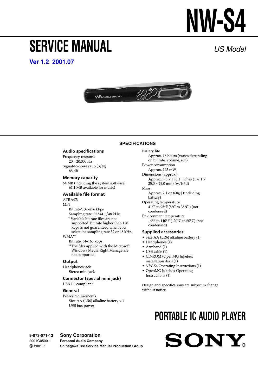
Sony nw s 4 service manual

This is the 32 pages manual for sony nw s 4 service manual.
Read or download the pdf for free. If you want to contribute, please mail your pdfs to info@audioservicemanuals.com.

Page: 1 / 32
left right
sony nw s 4 service manual

Extracted text from sony nw s 4 service manual (Ocr-read)


Page 1

2 NW-S4 Network Walkman is trademark of Sony Corporation. OpenMG and its logo are trademarks of Sony Corporation. WALKMAN is a registered trademark of Sony Corporation. Microsoft, Windows, Windows NT, Windows Media, Windows Millennium Edition and their logos are trademarks or registered trademarks of Microsoft Corporation in the United States and/or other countries. US and foreign patents licensed from Dolby Laboratories. All other trademarks and registered trademarks are trademarks or registered trademarks of their respective holders. TGJL©ddOKddIONT©NTS CA S©RV"I"N7ddNOT©S .................................................. 3 2. GENERAL ...................................................................... 8 3. DISASSEMBLY 3-1. Disassembly Flow .............................................................. 9 3-2. Lower Case Assy ................................................................ 9 3-3. Jack Flexible Module, Jack (Small Type) (Water Proof) (J301) .......................... 10 3-4. MAIN Board .................................................................... 10 3-5. SUB Board ....................................................................... 11 4. DIAGRAMS 4-1. Block Diagram ................................................................. 13 4-2. Note for Printed Wiring Boards and Schematic Diagrams ........................................................ 14 4-3. Printed Wiring Board -“ MAIN Board -“ ......................... 15 4-4. Schematic Diagram -“ MAIN Board (1/2) -“ ................... 16 4-5. Schematic Diagram -“ MAIN Board (2/2) -“ ................... 17 4-6. Printed Wiring Boards -“ SUB Board -“ .......................... 18 4-7. Schematic Diagram -“ SUB Board -“ ............................... 19 4-8. IC Pin Function Description ............................................ 21 5. EXPLODED VIEWS 5-1. Upper Case Assy .............................................................. 25 5-2. Board Assy ....................................................................... 26 6. ELECTRICAL PARTS LIST ................................ 27Flexible Circuit Board Repairing - Keep the temperature of the soldering iron around 270 ËšC dur- ing repairing. - Do not touch the soldering iron on the same conductor of the circuit board (within 3 times). - Be careful not to apply force on the conductor when soldering or unsoldering. Notes on chip component replacement - Never reuse a disconnected chip component. - Notice that the minus side of a tantalum capacitor may be dam- aged by heat.