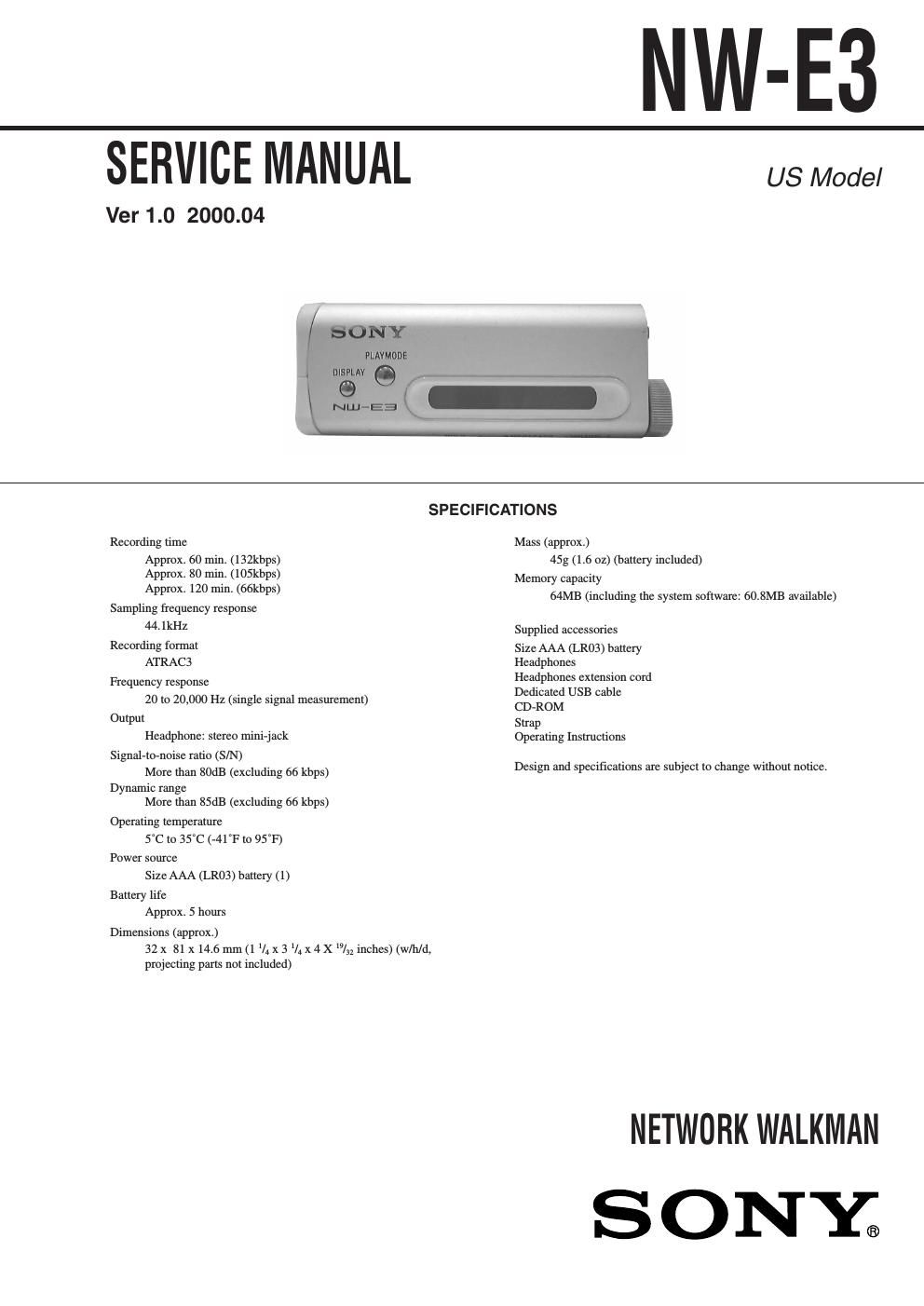
Sony nw e 3 service manual

This is the 20 pages manual for sony nw e 3 service manual.
Read or download the pdf for free. If you want to contribute, please mail your pdfs to info@audioservicemanuals.com.

Page: 1 / 20
left right
sony nw e 3 service manual

Extracted text from sony nw e 3 service manual (Ocr-read)


Page 1

-“ 2 -“ Specifications ............................................................................ 1 1. GENERAL ....................................................................... 3 2. DISASSEMBLY 2-1. Chassis ASSY ............................................................. 7 2-2. LID, Case .................................................................... 7 2-3. LCD Unit .................................................................... 8 2-4. Main Board, Power Board .......................................... 8 3. TEST MODE ................................................................... 9 4. DIAGRAMS 4-1. Block Diagrams ........................................................ 11 4-2. Printed Wiring Boards (Main Section) ..................... 13 4-3. Schematic Diagram (Main Section) ......................... 15 4-4. Schematic Diagram (Power Section) ........................ 20 4-5. Printed Wiring Boards (Power Section) ................... 23 5. EXPLODED VIEW 5-1. Main Section ............................................................. 25 5-2. Case Section ............................................................. 26 6. ELECTRICAL PARTS LIST .................................... 27 Flexible Circuit Board Repairing - Keep the temperature of the soldering iron around 270°C during repairing. - Do not touch the soldering iron on the same conductor of the circuit board (within 3 times). - Be careful not to apply force on the conductor when soldering or unsoldering. Notes on chip component replacement - Never reuse a disconnected chip component. - Notice that the minus side of a tantalum capacitor may be dam- aged by heat. TABLE OF CONTENTS - Replacement of CXD9534GG (IC710) used in the set requires a special tool. Therefore, it cannot be replaced.

Page 2

-“ 3 -“ SECTION 1 GENERAL LOCATION AND FUNCTION OF CONTROLS This section is extracted from instr uction manual. (front) (rear) To use the strap Display 1 Text/graphic information display 2 Play mode indication 3 AVLS indication 4 MEGA BASS indication 5 Battery remain indication 1 i (Headphones) jack 2 Display 3 PLAYMODE button 4 DISPLAY button 5 Bx (play/stop) button 6 Shuttle switch 7 VOLUME+/-“ button 8 MEGABASS/AVLS button 9 HOLD switch 0 Dedicated USB jack qa Strap hole for attaching the strap qs Battery compartment 23 5 1 4 1 2 3 45 6 7 8 9 0 qs qa