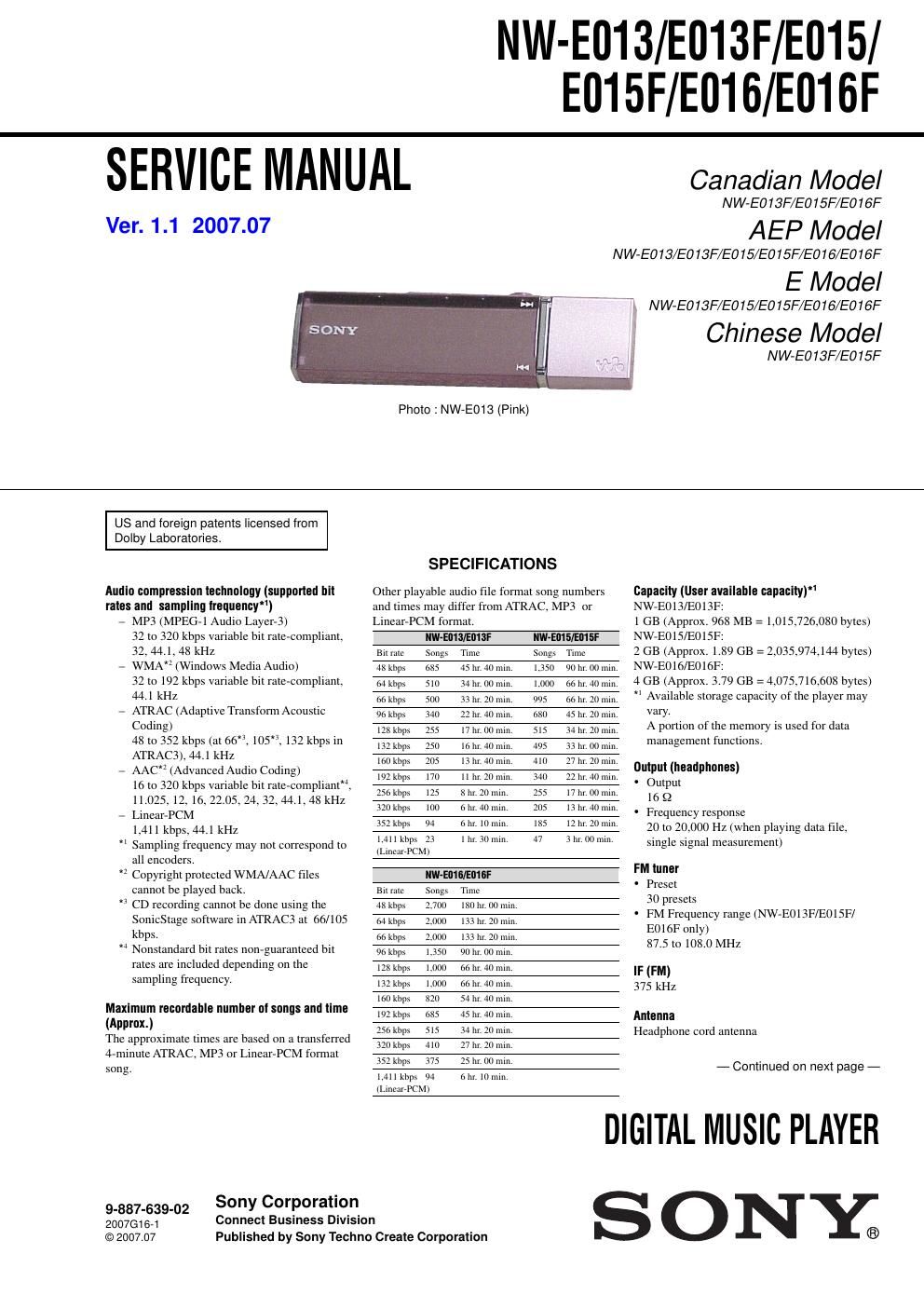
Sony nw e 013 service manual

This is the 34 pages manual for sony nw e 013 service manual.
Read or download the pdf for free. If you want to contribute, please mail your pdfs to info@audioservicemanuals.com.

Page: 1 / 34
left right
sony nw e 013 service manual

Extracted text from sony nw e 013 service manual (Ocr-read)


Page 1

2 NW-E013/E013F/E015/E015F/E016/E016F UNLEADED SOLDER Boards requiring use of unleaded solder are printed with the lead- free mark (LF) indicating the solder contains no lead. (Caution: Some printed circuit boards may not come printed withthe lead free mark due to their particular size) : LEAD FREE MARK Unleaded solder has the following characteristics. - Unleaded solder melts at a temperature about 40 °C higher than ordinary solder. Ordinary soldering irons can be used but the iron tip has to be applied to the solder joint for a slightly longer time. Soldering irons using a temperature regulator should be set to about 350 °C. Caution: The printed pattern (copper foil) may peel away if the heated tip is applied for too long, so be careful! - Strong viscosity Unleaded solder is more viscou-s (sticky, less prone to flow) than ordinary solder so use caution not to let solder bridges occur such as on IC pins, etc. - Usable with ordinary solder It is best to use only unleaded solder but unleaded solder may also be added to ordinary solder. Flexible Circuit Board Repairing - Keep the temperature of the soldering iron around 270 °C during repairing. - Do not touch the soldering iron on the same conductor of the circuit board (within 3 times). - Be careful not to apply force on the conductor when soldering or unsoldering. Notes on chip component replacement - Never reuse a disconnected chip component. - Notice that the minus side of a tantalum capacitor may be damaged by heat. Interface Headphone: Stereo mini Hi-Speed USB (USB 2.0 compliant) Operating temperature 5 ºC to 35 ºC (41 ºF to 95 ºF) Power source -Built-in rechargeable lithium-ion battery - USB power (from a computer through a USB connector of the player) Charging time USB-based charging Approx. 60 minutes Battery life (continuous playback)* 1 *1This is when Power Save Mode is set to Save ON Super, and Sound, VPT, Clear Stereo, or Dynamic Normali\ zer is set to off. The battery duration will vary depending on temperature and usage. NW-E013/E015/E016 NW-E013F/E015F/E016F Status of the player Playback at ATRAC 132 kbps Approximately 30 hours Approximately 30 hours Playback at ATRAC 128 kbps Approximately 27 hours Approximately 27 hoursPlayback at ATRAC 48 kbps Approximately 28 hours Approximately 28 hours Playback at MP3 128 kbps Approximately 28 hours Approximately 28 hours Playback at WMA 128 kbps Approximately 24 hours Approximately 24 hoursPlayback at AAC 128 kbps Approximately 28 hours Approximately 28 hours Playback at Linear-PCM 1,411 kbps Approximately 25 hours Approximately 25 hours At receiving FM broadcasting -“ Approximately 10 hours Display 3-line Color LCD Dimension (w/h/d, projecting parts not included) 82.9 × 22.4 × 13.6 mm (3 3/4 × 29/32 × 9/16 inches) Dimension (w/h/d) 83.1 × 22.8 × 14.2 mm (3 3/8 × 29/32 × 9/16 inches) Mass Approx. 29 g (Approx. 1.1 oz) Supplied Accessories - Headphones (1) - CD-ROM * 1 (1) - SonicStage software - Operation Guide (PDF file) - Quick Start Guide (1) - Precautions (1) - Troubleshooting (1) * 1Do not attempt to play this CD-ROM in an audio CD player. - Microsoft, Windows, Windows Vista and Windows Media are trademarks or registered trademarks of Microsoft Corporation in the United States and/or other countries. - Adobe and Adobe Reader are trademarks or registered trademarks of Adobe Systems Incorporated in the United States and/or other countries. - MPEG Layer-3 audio coding technology and patents licensed from Fraunhofer IIS and Thomson. - IBM and PC/AT are registered trademarks of International Business Machines Corporation. - Macintosh is a trademark of Apple Inc. - Pentium is a trademark or a registered trademark of Intel Corporation. - US and foreign patents licensed from Dolby Laboratories. - All other trademarks and registered trademarks are trademarks or registered trademarks of their respective holders. In this manual, TM and ® marks are not specified. This product is protected by certain intellectual property rights of Microsoft Corporation. Use or distribution of such technology outside of this product is prohibited without a license from Microsoft or an authorized Microsoft subsidiary. Program ©2007 Sony Corporation Documentation ©2007 Sony Corporation CAUTION Danger of explosion if battery is incorrectly replaced. Replace only with the same or equivalent type. Design and specifications are subject to change without notice.

Page 2

3 NW-E013/E013F/E015/E015F/E016/E016F TABLE OF CONTENTS 1. SERVICING NOTE ................................................... 4 2. GENERAL ................................................................... 6 3. DISASSEMBLY 3-1. Disassembly Flow ........................................................... 7 3-2. USB (Cover), USB (Holder), Ornament (Seesaw) .......... 8 3-3. Key (Seesaw) ................................................................... 8 3-4. Cabinet (Upper), Sheet (Shield), Cushion (A) ................ 9 3-5. Ornament (HP), Button (Operation), Cabinet (Lower) Assy ...................................................... 9 3-6. Plate (HP Ornament), Sheet (L), Sheet (LB), Sheet (Shield LCD), Sheet (T) ........................................ 10 3-7. MAIN Board, Mini Jack, USB Connector ...................... 10 3-8. LCD Unit ........................................................................\ . 11 3-9. Sheet Switch, Support (Seesaw) ...................................... 11 3-10. Lithium Ion Storage Battery, Sheet (Battery), Frame ..... 12 4. TEST MODE ............................................................... 13 5. DIAGRAMS 5-1. Block Diagram ................................................................ 16 5-2. Printed Wiring Board -“ MAIN Board (Side A) -“ ........... 17 5-3. Printed Wiring Board -“ MAIN Board (Side B) -“ ........... 18 5-4. Schematic Diagram -“ MAIN Board (1/3) -“ ................... 19 5-5. Schematic Diagram -“ MAIN Board (2/3) -“ ................... 20 5-6. Schematic Diagram -“ MAIN Board (3/3) -“ ................... 21 6. EXPLODED VIEWS 6-1. Outer Parts Section .......................................................... 22 6-2. Inner Parts Section ........................................................... 23 7. ELECTRICAL PARTS LIST .................................. 30