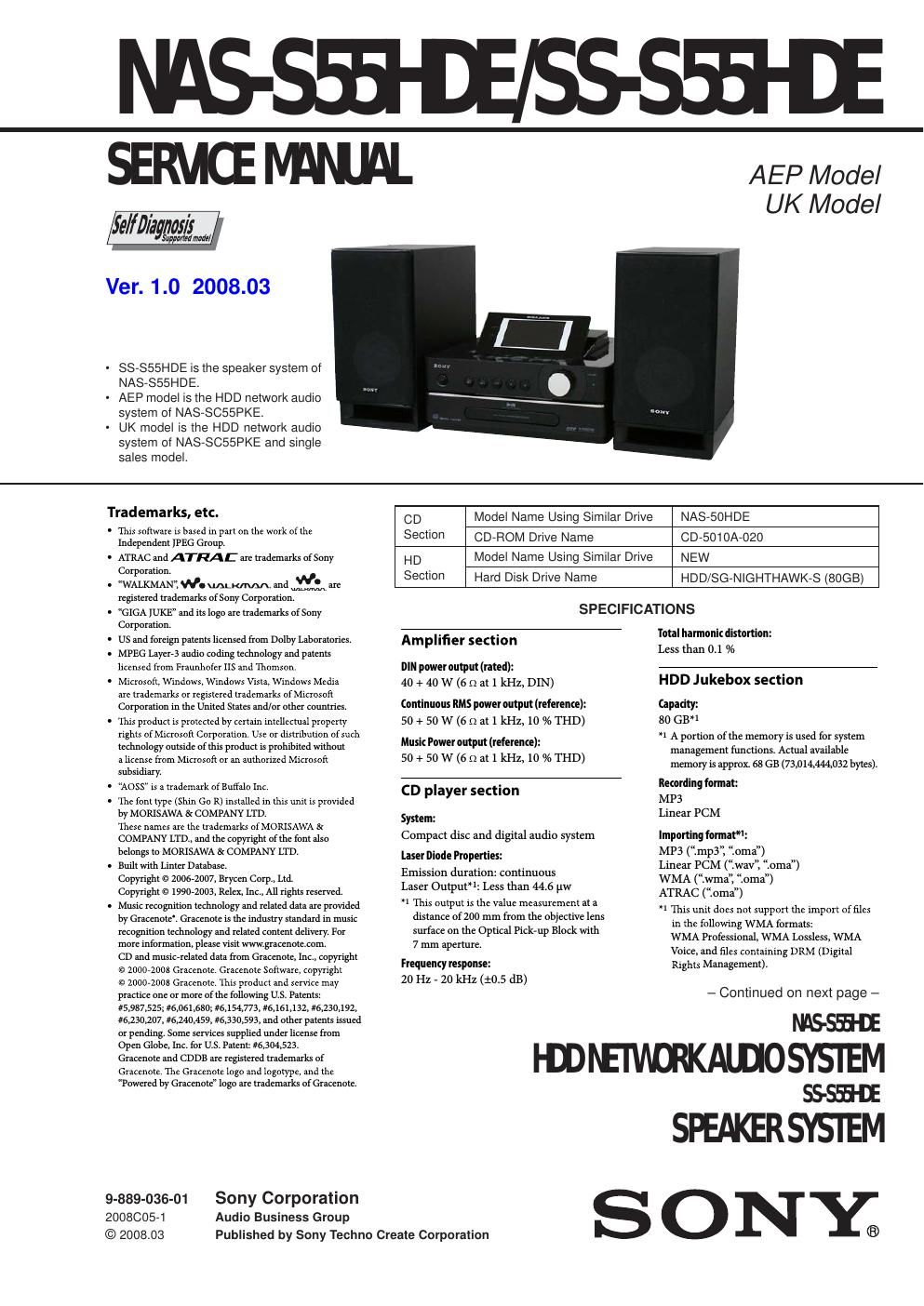
Sony nas s 55 hde service manual

This is the 106 pages manual for sony nas s 55 hde service manual.
Read or download the pdf for free. If you want to contribute, please mail your pdfs to info@audioservicemanuals.com.

Page: 1 / 106
left right
sony nas s 55 hde service manual

Extracted text from sony nas s 55 hde service manual (Ocr-read)


Page 1

NAS-S55HDE/SS-S55HDE 2 218.640 MHz 11B 220.352 MHz 11C 222.064 MHz 11D 223.936 MHz 12A 225.648 MHz 12B 227.360 MHz 12C 229.072 MHz 12D 230.784 MHz 13A 232.496 MHz 13B 234.208 MHz 13C 235.776 MHz 13D 237.488 MHz 13E 239.200 MHz 13F Inputs/Outputs MONITOR OUT (phono jack): 1 Vp-p, 75 Ωunbalanced (NTSC) AUDIO IN (top: stereo mini jack) / AUDIO IN (rear: phono jacks): Voltage 0.8 V (standard), impedance 10 k Ω (top) / 1.5 V (low sensitivity), impedance 10 k Ω (rear) NETWORK port: 10BASE-T/100BASE-TX USB port: USB type A, Hi-Speed USB for connecting USB devices such as WALKMAN DMPORT Output voltage: DC 5 V mA PHONES jack (stereo mini jack): Accepts headphones of 8 Ωor more Speaker Speaker system: Speaker units: Woofer: 120 mm, cone type Nominal impedance: 6 Ω Dimensions (w/h/d) Approx. 140 × 283 × 245 mm (including a grille) Mass Approx. 2.8 kg net per speaker Wireless adaptor Interface: IEEE802.11 b/g-compliant 2.4 GHz radio frequency band General Power requirements: 230 V AC, 50/60 Hz Power consumption: 65 W (0.5 W or lower at the standard (power save) mode) Dimensions (w/h/d) (including projecting parts and controls): UK model: With the display window lowered: approx. 285 × 143 × 317.4 mm With the display window raised: approx. 285 × 193 × 317.4 mm Models except the UK model With the display window lowered: approx. 285 × 143 × 311 mm With the display window raised: approx. 285 × 193 × 311 mm Mass (Approx.): 5.0 kg Operating temperature: +5 oC (+41 oF) to +35 oC (+95 oF) Operating humidity: 25 % to 80 % Supplied accessories: subjecttochangewithoutnotice. Maximum recording time (measured with ATRAC 48 kbps): About 3,400 h Maximum number of tracks: 40,000 FM tuner section Tuner: FM stereo tuner Frequency range: 87.5 - 108.0 MHz (50 kHz step) Antenna: FM wire antenna Antenna terminals: 75 Ω unbalanced Intermediate frequency: 10.7 MHz AM tuner section Tuner: AM tuner Frequency range: 531 - 1,602 kHz (with the interval set at 9 kHz) Antenna: AM loop antenna Antenna terminals: External antenna terminal Intermediate frequency: 450 kHz DAB tuner section (UK model only) Tuner: DAB stereo tuner Antenna: DAB wire antenna Antenna terminals: 75 Ω unbalanced Frequency range: Band-III: 174.928 (5A) - 239.200 (13F) MHz DAB frequency table (Band-III): Frequency Label 174.928 MHz 5A 176.640 MHz 5B 178.352 MHz 5C 180.064 MHz 5D 181.936 MHz 6A 183.648 MHz 6B 185.360 MHz 6C 187.072 MHz 6D 204.640 MHz 9B 206.352 MHz 9C 208.064 MHz 9D 209.936 MHz 10A 211.648 MHz 10B 213.360 MHz 10C 215.072 MHz 10D 216.928 MHz 11A Wireless adaptor (1) USB extension cable (1) Speaker codes (2) Speaker pads (8) AM loop antenna (1) FM wire antenna (1) DAB wire antenna (1) (for the UK model only) Remote control (1) R 6 (size AA) batteries (2) Operating Instructions (this manual) GNU General Public License/GNU Lesser General Public License (1) License agreement for SONY software (1) Frequency Label 188.928 MHz 7A 190.640 MHz 7B 192.352 MHz 7C 194.064 MHz 7D 195.936 MHz 8A 197.648 MHz 8B 199.360 MHz 8C 201.072 MHz 8D 202.928 MHz 9A SAFETY-RELATED COMPONET WARNING! COMPONENTS IDENTIFIED BY MARK 0 OR DOTTED LINE WITH MARK 0 ON THE SCHEMATIC DIAGRAMS AND IN THE PARTS LIST ARE CRITICAL TO SAFE OPERATION. REPLACE THESE COMPONENTS WITH SONY PARTS WHOSE PART NUMBERS APPEAR AS SHOWN IN THIS MANUAL OR IN SUPPLEMENTS PUBLISHED BY SONY. Notes on chip component replacement - Never reuse a disconnected chip component. - Notice that the minus side of a tantalum capacitor may be dam- aged by heat. Flexible Circuit Board Repairing - Keep the temperature of soldering iron around 270 °C during repairing. - Do not touch the soldering iron on the same conductor of the circuit board (within 3 times). - Be careful not to apply force on the conductor when soldering or unsoldering. This appliance is classified as a CLASS 1 LASER product. This marking is located on the rear exterior. CAUTION Use of controls or adjustments or performance of procedures other than those speci fi ed herein may result in hazardous radiation exposure. About the self-diagnosis function A service number consisting of E 00 11) appears in the display when the self-diagnosis function activates to prevent abnormal operation. When this service number appears, consult the local authorized service facility and report this service number to the service personnel.

Page 2

NAS-S55HDE/SS-S55HDE 3 1. SERVICING NOTES ............................................. 4 2. GENERAL .................................................................. 9 3. DISASSEMBLY 3-1. Disassembly Flow ........................................................... 12 3-2. Panel (Side L/R) Assy ..................................................... 13 3-3. Cover (Base) Assy, Panel (Top) Block ........................... 13 3-4. PANEL (TOP) Board, LCD Block .................................. 14 3-5. Module (LCD) ................................................................ 14 3-6. Panel (Front) Block ......................................................... 15 3-7. Knob (VOL), PANEL (TOP) Board ............................... 15 3-8. Chassis (Top) .................................................................. 16 3-9. MOTHER Board ............................................................. 16 3-10. SP/DM Board .................................................................. 17 3-11. MAIN Board ................................................................... 17 3-12. Hard Disc Drive .............................................................. 18 3-13. Fan. DC (M101), Chassis (MID) .................................... 18 3-14. CD Block ........................................................................\ 19 3-15. Note the CD-ROM Drive and Insulating (CD) Replacing .............................................. 19 3-16. CD-ROM Drive (CD-5010A-020) .................................. 20 3-17. Position of Frrite Core for Speaker Cord ........................ 20 4. TEST MODE ............................................................ 21 5. DIAGRAMS 5-1. Block Diagram - MAIN Section - ................................... 23 5-2. Block Diagram - PANEL, DSP Section -........................ 24 5-3. Block Diagram - AUDIO Section - ................................. 25 5-4. Block Diagram - POWER SUPPLEY Section - ............. 26 5-5. Printed Wiring Board - MOTHER Board (Component Side) - .......................... 28 5-6. Printed Wiring Board - MOTHER Board (Conductor Side) - ........................... 29 5-7. Schematic Diagram - MOTHER Board (1/10) - ............. 30 5-8. Schematic Diagram - MOTHER Board (2/10) - ............. 31 5-9. Schematic Diagram - MOTHER Board (3/10) - ............. 32 5-10. Schematic Diagram - MOTHER Board (4/10) - ............. 33 5-11. Schematic Diagram - MOTHER Board (5/10) - ............. 34 5-12. Schematic Diagram - MOTHER Board (6/10) - ............. 35 5-13. Schematic Diagram - MOTHER Board (7/10) - ............. 36 5-14. Schematic Diagram - MOTHER Board (8/10) - ............. 37 5-15. Schematic Diagram - MOTHER Board (9/10) - ............. 38 5-16. Schematic Diagram - MOTHER Board (10/10) - ........... 39 5-17. Printed Wiring Board - MAIN Board (Component Side) - ................................ 40 5-18. Printed Wiring Board - MAIN Board (Conductor Side) - .................................. 41 5-19. Schematic Diagram - MAIN Board (1/4) - ..................... 42 5-20. Schematic Diagram - MAIN Board (2/4) - ..................... 43 5-21. Schematic Diagram - MAIN Board (3/4) - ..................... 44 5-22. Schematic Diagram - MAIN Board (4/4) - ..................... 45 5-23. Printed Wiring Board - DAB PS Board (UK Model) - ... 46 5-24. Schematic Diagram - DAB PS Board (UK Model) - ...... 46 5-25. Printed Wiring Board - SP/DM Board - .......................... 47 5-26. Schematic Diagram - SP/DM Board - ............................ 47 5-27. Printed Wiring Board - PANEL (FRONT) Board - ........ 48 5-28. Schematic Diagram - PANEL (FRONT) Board - ........... 48 5-29. Printed Wiring Board - PANEL (TOP) Board - .............. 49 5-30. Schematic Diagram - PANEL (TOP) Board - ................. 49 5-31. Printed Wiring Board - LCD Board - .............................. 50 5-32. Schematic Diagram - LCD Board - ................................ 51 5-33. Printed Wiring Boards - AUDIO INPUT/OUTPUT Section -............................. 52 TABLE OF CONTENTS 5-34. Schematic Diagram - AUDIO INPUT/OUTPUT Section -............................. 52 6. EXPLODED VIEWS 6-1. Front Panel Section ......................................................... 82 6-2. Panel (Top) Section ......................................................... 83 6-3. LCD Section ................................................................... 84 6-4. MAIN Board, MOTHER Board Section ........................ 85 6-5. HDD Section ................................................................... 86 6-6. CD-ROM Drive, Chassis Section ................................... 87 6-7. Speaker Section (SS-S55HDE) ....................................... 88 7. ELECTRICAL PARTS LIST .............................. 89