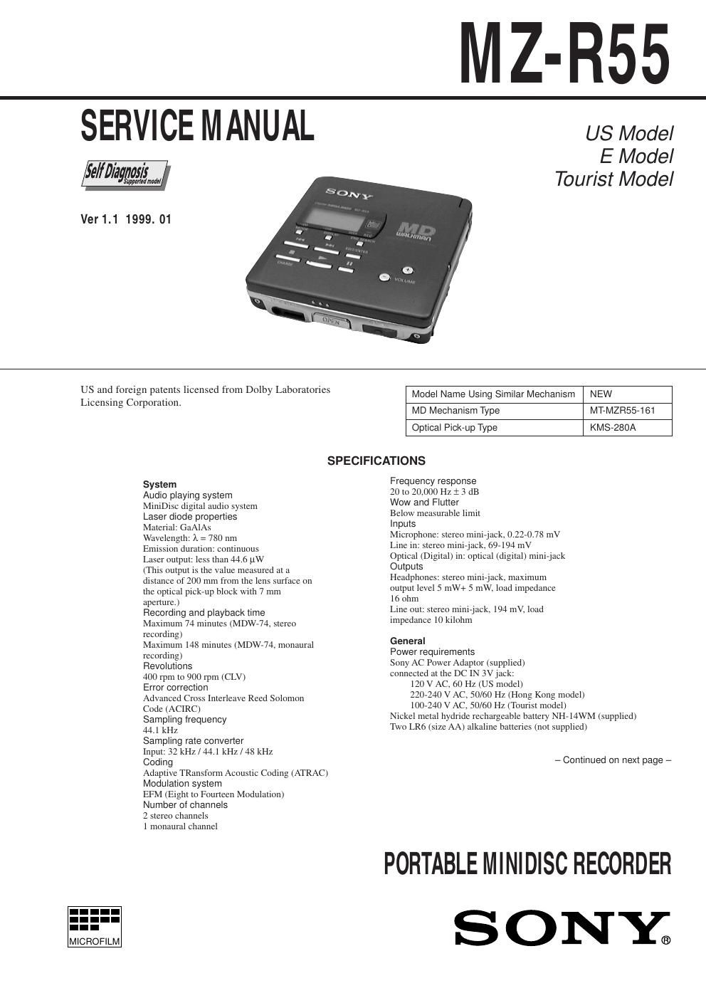
Sony mz r55

This is the 44 pages manual for sony mz r55.
Read or download the pdf for free. If you want to contribute, please mail your pdfs to info@audioservicemanuals.com.

Page: 1 / 44
left right
sony mz r55

Extracted text from sony mz r55 (Ocr-read)


Page 1

Ð 2 Ð Battery operation time Batteries Recording Playback NH-14WM nickel Approx. Approx. metal hydride 2.5 hours 4 hours rechargeable battery Two LR6 (SG) Approx. Approx. Sony alkaline dry batteries 5 hours 10 hours NH-14WM + Two LR6 (SG)Approx. Approx. 9.5 hours 16 hours Dimensions Approx. 78.9 ´ 18.9 ´ 84 mm (w/h/d) (3 1/8 ´ 3/4 ´ 3 3/8 in.) Mass Approx. 147 g (5.2 oz) the recorder only Approx. 190 g (6.7 oz) incl. a recordable MD, and NH-14WM nickel metal hydride rechargeable battery Supplied accessories AC power adaptor AC-MZR55 (1) Headphones with a remote control MDR-A34SP (US model)/MDR-E838SP (Hong Kong, Tourist model) and RM-MZR55 (1) NH-14WM nickel metal hydride rechargeable battery (1) Dry battery case (1) Rechargeable battery carrying case (1) Carrying pouch (1) AC plug adaptor (1) (Tourist model only) Design and specifications are subject to change without notice. SAFETY-RELATED COMPONENT WARNING!! COMPONENTS IDENTIFIED BY MARK ! OR DOTTED LINE WITH MARK ! ON THE SCHEMATIC DIAGRAMS AND IN THE PARTS LIST ARE CRITICAL TO SAFE OPERATION. REPLACE THESE COMPONENTS WITH SONY PARTS WHOSE PART NUMBERS APPEAR AS SHOWN IN THIS MANUAL OR IN SUPPLEMENTS PUBLISHED BY SONY. Flexible Circuit Board Repairing ¥ Keep the temperature of the soldering iron around 270°C during repairing. ¥ Do not touch the soldering iron on the same conductor of the circuit board (within 3 times). ¥ Be careful not to apply force on the conductor when soldering or unsoldering. Notes on chip component replacement ¥ Never reuse a disconnected chip component. ¥ Notice that the minus side of a tantalum capacitor may be damaged by heat. Precautions for Laser Diode Emission Check When checking the emission of the laser diode during adjust- ments, never view directly downwards as this may lead to blindness. Precautions for Using Optical Pick-up (KMS-280A) As the laser diode inside the optical pick-up damages by static electricity easily, solder the laser tap of the Optical pick-up flexible board when handling. Also take the necessary measures to prevent damages by static electricity. Handle the Optical pick- up flexible board with care as it breaks easily. Laser tap Optical Pick-up flexible board

Page 2

Ð 3 Ð upper panel assy MAIN board S801tape 1. GENERAL ....................................................................... 4 2. SELF-DIAGNOSTIC 2-1. General ..................................................................... 5 2-2. Test Mode Setting ..................................................... 5 2-3. Operation in Test Mode Setting ................................ 5 2-4. Releasing the Test Mode ........................................... 5 2-5. Self-Diagnostic Mode ............................................... 5 2-6. Clearing the Error Indication Code and Total Recording Time ........................................ 6 3. DISASSEMBLY 3-1. Bottom Panel Assy ................................................... 7 3-2. Connector ................................................................. 7 3-3. Upper Panel Block Assy ........................................... 8 3-4. LCD Block Assy ....................................................... 8 3-5. Ornamental Belt Block Assy .................................... 9 3-6. Main Board ............................................................... 9 3-7. Chassis (Main) Assy ............................................... 10 3-8. OP Block Assy ........................................................ 10 3-9. Holder Assy ............................................................ 11 TABLE OF CONTENTS 4. TEST MODE 4-1. General ................................................................... 12 4-2. Test Mode Setting ................................................... 12 4-3. Test Mode Structure ............................................... 12 4-4. Manual Mode ......................................................... 12 4-5. Overall Adjustment Mode ...................................... 15 4-6. Hybrid Mode, Key Check Mode ............................ 16 5. ELECTRICAL ADJUSTMENTS ........................... 17 6. DIAGRAMS 6-1. IC Pin Descriptions ................................................ 21 6-2. Block Diagram Ð Servo Section Ð .......................... 25 6-3. Block Diagram Ð Audio Section Ð .......................... 27 6-4. Block Diagram Ð System Control Section Ð ........... 29 6-5. Printed Wiring Board (-11) ..................................... 31 6-6. Printed Wiring Board (-12) ..................................... 34 6-7. Schematic Diagram Ð Main Section (1/3) Ð ........... 37 6-8. Schematic Diagram Ð Main Section (2/3) Ð ........... 40 6-9. Schematic Diagram Ð Main Section (3/3) Ð ........... 43 7. EXPLODED VIEWS 7-1. Panel Section .......................................................... 51 7-2. Chassis Section ....................................................... 52 7-3. Mechanism Deck Section ....................................... 53 8. ELECTRICAL PARTS LIST ................................... 54 SERVICING NOTE 1) When repairing this device with the power on, if you remove the main board or open the upper panel assy, this device stops working. In this case, you can work without the device stopping by fastening the hook of the DOOR OPEN switch (S801) with tape. 2) This set is designed to perform automatic adjustment for each adjustment and write its value to EEPROM. Therefore, when EEPROM (IC801) has been replaced in service, be sure to per- form automatic adjustment and write resultant values to the new EEPROM. Refer to page 12 for details.