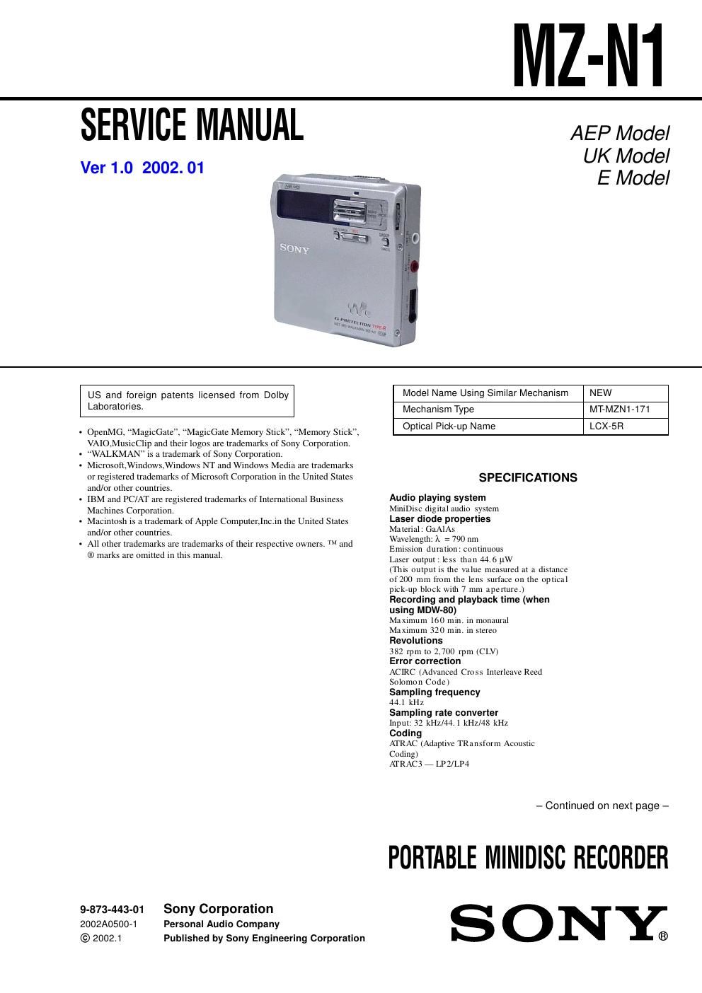
Sony mz n 1 service manual

This is the 64 pages manual for sony mz n 1 service manual.
Read or download the pdf for free. If you want to contribute, please mail your pdfs to info@audioservicemanuals.com.

Page: 1 / 64
left right
sony mz n 1 service manual

Extracted text from sony mz n 1 service manual (Ocr-read)


Page 1

2 MZ-N1 SAFETY-RELATED COMPONENT WARNING!! COMPONENTS IDENTIFIED BY MARK 0 OR DOTTED LINE WITH MARK 0 ON THE SCHEMATIC DIAGRAMS AND IN THE PARTS LIST ARE CRITICAL TO SAFE OPERATION. REPLACE THESE COMPONENTS WITH SONY PARTS WHOSE PART NUMBERS APPEAR AS SHOWN IN THIS MANUAL OR IN SUPPLEMENTS PUB- LISHED BY SONY. Modulation systemE FM (E ight to Four teen Modula tion) Frequency response2 0 to 20, 000 Hz ± 3 dBWow and FlutterBelow measurable limit Inputs 1) MIC : stereo mini-ja c k (m inim um inpu t leve l 0. 25 m V) Line in : stereo m ini-jack fo r anolog input (m inim um inpu t level 49 m V ) op tica l (d igita l) min i-ja c k fo r opt ical (d ig ital ) input Outputsi/LINE OUT 2): s tereo min i-jac k (ded icated re mo te c o n tro l ja c k)/194 m V (1 0 kohm ) Maximum ou t put (DC) 2) Headphones: 5 mW + 5 m W (1 6 o h m) Power requirementSony AC Power Adaptor connected at the DC IN 3V ja ck (c ountry m odel in p a rentheses): 220 V AC, 50/60 Hz (Continental Europe) 230 - 240 V AC, 50 Hz (U.K. and Hong Kong) 100 - 240 V AC, 50/60 Hz (Other countries) Battery life 1) When recording 2) (Unit: approxi.hours)(JEITA 3)) Batteries SP Stere oLP2 Stere oLP4 Stereo Nickel m e ta l hy dride rechargeable battery 4) 12 17 21 LR6 (S G) Sony al kaline dry battery 5) 12 19 23 Nickel metal hydride rechargeable battery 4) + On e LR6 (SG) 5) 30 43 52 Th e recorder: Nicke l metal hydride rechargeable battery NH-14 WM(A) 1. 2V 135 0 m Ah (MIN) Ni- MH LR6 (S G) a lkaline battery USB cradle: AC power adaptor DC 3V DimensionsAppr ox. 77 .7 × 71.4 ×16.4 mm (w/h /d) (3 1/8 × 27/8 × 21/32 in.) MassAppr ox. 87 g (3 .0 oz ) the recorder only 1)The LINE IN (O P T) jack is us ed to co nnect e ither a digital (optica l) ca ble o r a line (analog) cable. 2)The i/LINE O UT ja c k connects either headphones/earphones o r a line cable. De si gn and specitications a re subject to ch ange without not ice. Supplied accessoriesAC power adaptor (1) Headphones/earphones with a remote control (1) Optical cable (1 ) US B ca ble (1 ) Nickel metal hydride rechargeable battery NH-14WM(A) (1) C D-R O M (1 )* Dry battery case (1) Rechargeable battery carrying case (1) Carrying pouch/carrying case with a belt clip (1) *Do not play a CD-ROM on an a udio CD playe r. 1)The battery life m a y be shorter due to operating co ndit ions a nd th e temperature of the location. 2)Whe n you record , use a fully charged rechargeable battery. Recording time may diffe r according to the a lka line batteries. 3)Measured in accordance with the J E ITA (J a p a n Ele c tronic s a nd In fo rm a tion Technology Industries Association) standard. 4)Whe n u s ing a 100% fu lly c h a rge d nickel metal hyd ride rech argeab le ba ttery (NH- 14WM(A)). 5)Whe n us ing a S ony LR6 (S G) STAMINA a lka line dr y ba tte ry (p roduc ed in Ja pan) . When playing (Unit Batteries S P StereoLP2 StereoLP4 Stere o Nickel m etal hydrid e rechargeable battery 2) 30 38 4 2 LR6 (S G) Sony alkaline dry battery 3) 44 52 6 2 Nickel m etal hydrid e rechargeable battery 2) + On e LR6 (SG) 3) 79 95 1 10 1)Measured in accordance woth the J E ITA (Japan Electronics and Information Technology Industries Association) standard.2)Wh e n us ing a 1 00% fu lly c harged nickel metal hyd ride rechargeable battery (NH- 14WM(A)).3)Wh e n using a Sony LR6 (S G) STAMINA a lka line dr y battery (pro duced in Ja pan) : approxi.hours)(JEITA 1))

Page 2

3 MZ-N1 TABLE OF CONTENTS 1. SERVICING NOTES ............................................... 4 2. GENERAL ................................................................... 5 3. DISASSEMBLY 3-1. Disassembly Flow ........................................................... 6 3-2. Bottom Panel Assy .......................................................... 7 3-3. Upper Panel Section ........................................................ 7 3-4. LCD Module, Upper Panel Assy .................................... 8 3-5. MAIN Board Section ...................................................... 8 3-6. Battery Case Assy, MAIN Board .................................... 9 3-7. MD Mechanism Deck (MT-MZN1-171), Chassis Assy .................................................................... 9 3-8. OP Service Assy (LCX-5R) ............................................ 10 3-9. Holder Assy ..................................................................... 11 3-10. DC Motor (Sled) (M602) ................................................ 11 3-11. DC SSM18B Motor (Spindle) (M601), DC Motor (Over Write Head UP/DOWN) (M603) ....... 12 4. TEST MODE .............................................................. 13 5. ELECTRICAL ADJUSTMENTS ......................... 19 6. DIAGRAMS 6-1. Block Diagram -“ SERVO/USB Section -“...................... 30 6-2. Block Diagram -“ AUDIO Section -“............................... 31 6-3. Block Diagram -“ DISPLAY/KEY CONTROL/ POWER SUPPLY Section -“........................................... 32 6-4. Note for Printed Wiring Board and Schematic Diagrams ....................................................... 33 6-5. Printed Wiring Board -“ MAIN Board (Component Side) -“............................. 34 6-6. Printed Wiring Board -“ MAIN Board (Conductor Side) -“............................... 35 6-7. Schematic Diagram -“ MAIN Board (1/4) -“.................. 36 6-8. Schematic Diagram -“ MAIN Board (2/4) -“.................. 37 6-9. Schematic Diagram -“ MAIN Board (3/4) -“.................. 38 6-10. Schematic Diagram -“ MAIN Board (4/4) -“.................. 39 6-11. IC Pin Function Description ........................................... 46 7. EXPLODED VIEWS 7-1. Upper Panel Section ........................................................ 53 7-2. Bottom Panel Section ...................................................... 54 7-3. Chassis Section ............................................................... 55 7-4. MAIN Board Section ...................................................... 56 7-5. MD Mechanism Deck Section (MT-MZN1-171) .......... 57 8. ELECTRICAL PARTS LIST ............................... 58 CAUTION Use of controls or adjustments or performance of procedures other than those specified herein may result in hazardous ra- diation exposure. Notes on chip component replacement -Never reuse a disconnected chip component. -Notice that the minus side of a tantalum capacitor may be dam- aged by heat. Flexible Circuit Board Repairing -Keep the temperature of the soldering iron around 270 ËšC dur- ing repairing. -Do not touch the soldering iron on the same conductor of the circuit board (within 3 times). -Be careful not to apply force on the conductor when soldering or unsoldering. UNLEADED SOLDER Boards requiring use of unleaded solder are printed with the lead- free mark (LF) indicating the solder contains no lead. (Caution: Some printed circuit boards may not come printed with the lead free mark due to their particular size) : LEAD FREE MARK Unleaded solder has the following characteristics. -Unleaded solder melts at a temperature about 40 ËšC higher than ordinary solder. Ordinary soldering irons can be used but the iron tip has to be applied to the solder joint for a slightly longer time. Soldering irons using a temperature regulator should be set to about 350 ËšC . Caution: The printed pattern (copper foil) may peel away if the heated tip is applied for too long, so be careful! -Strong viscosity Unleaded solder is more viscous (sticky, less prone to flow) than ordinary solder so use caution not to let solder bridges occur such as on IC pins, etc. -Usable with ordinary solder It is best to use only unleaded solder but unleaded solder may also be added to ordinary solder. On power sources -Use house c u rre nt, nikel metal hyd ride rechargeable battery, LR6 (S G ) battery, or car battery. - For use in your house: For the s uppl ied battery char ging s ta n d, use the AC po wer adaptor s uppl ied with th is recorder. Do not use an y other AC po wer adaptor s ince it m a y cause th e reco rd er to m alfuncti on. Polarity of the plug