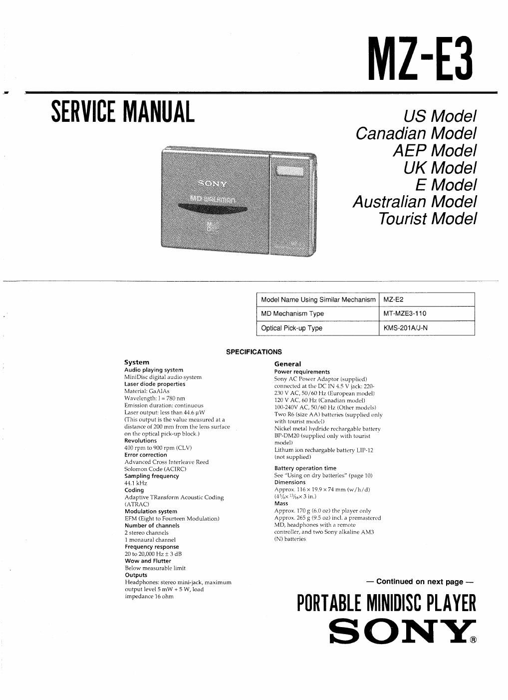
Sony mz e 3 service manual

This is the 44 pages manual for sony mz e 3 service manual.
Read or download the pdf for free. If you want to contribute, please mail your pdfs to info@audioservicemanuals.com.

Page: 1 / 44
left right
sony mz e 3 service manual

Extracted text from sony mz e 3 service manual (Ocr-read)


Page 1

MZ-E3

SERVICE MANUAL

US Model
Canadian Model

AEP Model
UK Model
E Model

Australian Model

Tourist Model

Model Name Using Similar Mechanism

MZ-E2

MD Mechanism Type

MT-MZE3»1 10

Optical Pick-up Type

KMS-201A/J-N

SPECIFICATIONS

System

Audio playing system

MiniDisc digital audio system

Laser diode properties

Material: GaAlAs

Wavelength: 780 nm

Emission duration: continuous

Laser output: less than 44.6 uW

(This output is the value measured at a
distance of 200 mm from the lens surface
on the optical pick-up block.)
Revolutions

400 rpm to 900 rpm (CLV)

Error correction

Advanced Cross lnterleave Reed
Solomon Code (ACIRC)

Sampling frequency

44] kHz

Coding

Adaptive TRansform Acoustic Coding
(ATRAC)

Modulation system

EFM (Eight to Fourteen Modulation)
Number of channels

2 stereo channels

] monaural channel

Frequency response

20 lo 20,000 Hz 1 3 dB

Wow and Flutter

Below measurable limit

Outputs

Headphones: stereo mini-jack, maximum
nutpul level 5 mW + 5 W, load
impedance lb ohm

General

Power requirements

Sony AC Power Adaptor (supplied)
connected at the DC IN 4.5 V jack: 220-
230 V AC, 50/60 Hz (European model)
120 V AC, 60 Hz (Canadian model)

1007240V AC, 50/61le (Other models)

Two R6 (size AA) batteries (Supplied only

wlth tourist model)

Nickel metal hydride rechargable bntlcry

BP-DMZO(5t1pplled only With luurlsl
model)

Lithum IOII rechargable battery LIl»12
(not supplied)

Battery operation time

See sing on dry batteries" (page l0)
Dimensions

Approx, no x199 X 74 mm (w/h/d)

(454x /ng 3 in.)

Mass

Approx l70 g (6.0 02) the player only

Approx. 265 g (9.5 oz) incl. 3 premastcrcd

MD, headphones with a remote
controller, and two Sony alkaline AM3
IN) batteries

- Contlnued on next page -

PORTABLE MINIDISC PLAYER
S O NEG

Page 2

Supplied accessories

AC power adaptor (I)

Headphones with a remote controller (1)
R6 (size AA) alkaline batteries (2,
supplied only with tourist model)
Nickel metal hydride rechargeable
battery (1, supplied only with tourist
model)

Battery Case (1, for LIP-12 Lithiumrioll
Battery)

Carrying case (1)

Optional accessories

BP-DMZO Nickel Metal Hydride
Rechargeable Battery

LIP-12 Lithium-ion Rechargeable Battery
ACR-MZéOA AC Power AdaptDr/
Battery Charger

CPA-8 Car Connecting Pack

MDR-DSS, MDR-D77 Stereo Headphones
SRSrASU Sony Active Speakers

CK-MD4 MinlDisc Carrying Case
CK-MDIO MiniDisc Filing Box

' ACPAMZfiOA can only be used as a
battery charger. It cannot be used as an
AC power adaptor with this player,

Your dealer may not handle some of the
above listed accessories. Please ask the
dealer for detailed information about the
accessories in your country.

us and foreign patents licensed from
Dolby Laboratories Licensing
Corporation,

Design and specifications are suhiect to
change without notice.

For Customers in Europe

CLASS 1 LASER PRODUCT
LUOKAN t LASERLAITE

KLASS I LASERAPPARAT

This MiniDisc Player is classified as a
CLASS] LASER product.

The CLASS I LASER PRODUCT label is
located on the bottom exterior.

For Customers in Canada

This Class B digital apparatus meets all
requirements of the Canadian
Interference-Causing Equipment
Regulations.

CLASS 1 LASER PRODUCT
LUOKAN 1 LASERLAITE

KLASS I LASEHAFPARAT

This MiniDisc Player is classified as a CLASS 1
LASER product.

The CLASS I LASER PRODUCT label is localEd
on the bottom exterior.

For Customers in Australia

If the supply cord of AC power adaptor is
damaged the AC power adaptor must be
returned to the manufacturer of his agent for the
cord to be replaced.

"MD WALKMAN" is a trademark of Sony
Corporation.

Notes on chip component replacement

a

.

Never reuse a disconnected chip component,
Notice that the minus side of a tantalum capacitor may be
damaged by heat.

Flexible Circuit Board Repairing

0

Keep the temperature of the soldering iron around 270 °C
during repairing.

Do not touch the soldering iron on the same conductor ofthe
circuit board (within 3 times).

Be Careful not to apply force on the conductor when soldering
or unsoldering.

SAFETY-RELATED COMPONENT WARNING I!

COMPONENTS IDENTIFIED BY MARK A 0R DOTTED

LINE WITH MARK A ON THE SCHEMATIC DIAGRAMS
AND IN THE PARTS LIST ARE CRITICAL TO SAFE

OPERATION. REPLACE THESE COMPONENTS WITH
SONY PARTS WHOSE PART NUMBERS APPEAR AS
SHOWN IN THIS MANUAL OR IN SUPPLEMENTS
PUBLISHED BY SONY.

ATTENTION AU COMPOSANT AYANT RAPPORT
A LA sEcuanEll

LEs COMPOSANTS IDENTIFIES PAR UNE MAROUE A
sun LES DIAGRAMMES SCHEMATIQUEs ET LA LISTE
DES PIECES SONT CHITIQUES POUR LA sEcurtrrE'
DE FONCTIONNEMENT. NE HEMPLACER CES
COMPOSANTS QUE PAR DES PIECES souv DONT
LEs NUMEROS sour DONNES DANS CE MANUEL ou
DANS LES SUPPLEMENTS PUBLIES PAR souv.

_2_