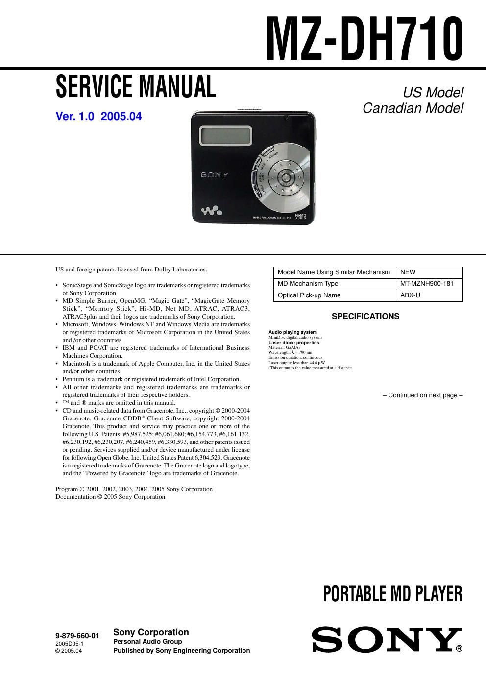
Sony mz dh 710 service manual

This is the 54 pages manual for sony mz dh 710 service manual.
Read or download the pdf for free. If you want to contribute, please mail your pdfs to info@audioservicemanuals.com.

Page: 1 / 54
left right
sony mz dh 710 service manual

Extracted text from sony mz dh 710 service manual (Ocr-read)


Page 1

2 MZ-DH710 Recording and playback timeList of the recording time for each disc When using a disc in Hi-MD mode When using a disc in MD modeWhen transferring from the computerRecording time 1)2) 1)Approximate time2)When transferring 4-minute tracks Codec/Bit rate 1GB Hi-MD disc80-minute standard disc74-minute standard disc60-minute standard disc Linear PCM/1.4Mbps 1 hour and 34 minutes28 minutes 26 minutes 21 minutes ATRAC3plus/256kbps 7 hours and 55 minutes2 hours and 20 minutes2 hours and 10 minutes1 hour and 40 minutes AT R AC3plus/64kbps 34 hours 10 hours and 10 minutes9 hours and 20 minutes7 hours and 40 minutes AT R AC3plus/ 48 kbps 45 hours 13 hours and 30 minutes12 hours and 30 minutes10 hours AT R AC3/132kbps 16 hours and 30 minutes4 hours and 50 minutes4 hours and 30 minutes3 hours and 40 minutes AT R AC3/105kbps 20 hours and 40 minutes6 hours and 10 minutes5 hours and 40 minutes4 hours and 40 minutes AT R AC3/66kbps 32 hours and 40 minutes9 hours and 50 minutes9 hours 7 hours and 20 minutes MP3/128kbps 17 hours 5 hours 4 hours and 30 minutes3 hours and 30 minutes When transferring from the computerRecording time 1)2) 1)Approximate time2)When transferring 4-minute tracks Codec/Bit rate 80-minute standard disc74-minute standard disc60-minute standard disc AT R AC(stereo)/292kbps 80 minutes 74 minutes 60 minutes ATRAC3/132, 105kbps 2 hours and 40 minutes2 hours and 28 minutes2 hours AT R AC3/66kbps 5 hours and 20 minutes4 hours and 56 minutes4 hours DimensionsApprox. 83.6 × 29.5 × 77.0 mm (w/h/d) (33/8 × 13/16 × 31/8 in.)(excluding projecting parts and controls) MassApproxSupplied accessoriesEarphones Dedicated USB cable CD-ROM (SonicStage/MD Simple Burner)* Recordable disc * Do not play a CD-ROM on an audio CD player.. 107 g (3.8 oz.) (the player only) Design and specifications are subject to change without notice. Revolutions350 rpm to 3,000 rpm (CLV)Error correctionHi-MD: LDC (Long Distance Code)/BIS (Burst Indicator Subcode) MD: ACIRC (Advanced Cross Interleave Reed Solomon Code) Sampling frequency44.1 kHzAudio formats supported by this player Linear PCM (44.1 kHz/16 bit) ATRAC3plus (Adaptive TRansform Acoustic Coding 3 plus) AT R A C 3 AT R A C MP3 (MPEG-1 Audio Layer-3/Sampling frequency 44.1 kHz/Bit rate 32 - 320 kbps (constant/variable bit rate)) Modulation systemHi-MD: 1-7RLL (Run Length Limited)/PRML (Partial Response Maximum Likelihood) MD: EFM (Eight to Fourteen Modulation) Frequency response20 to 20,000 Hz ± 3 dBOutputsi: stereo mini-jackMaximum output (DC)Headphones: 5 mW + 5 mW (16 -„¦) Power requirementsOne LR6 (size AA) alkaline battery (not supplied) Operating temperature+5°C (+41°F) to +35°C (+95°F)Battery operation time When playing continuously in MD mode (Unit: approx. hours) (JEITA) Battery life 1) When playing continuously in Hi-MD mode (Unit: approx. hours) (JEITA 2)) 1)When using a new Sony LR6 (size AA) alkaline dry battery (produced in Japan)2)Measured in accordance with the JEITA (Japan Electronics and Information Te chnology Industries Association) standard. Disc type Linear PCM Hi-SP Hi-LP MP3 3) 3)Tracks transferred at 128 kbps. 1GB Hi-MD disc 9.5 16.5 19.5 19.0 60/74/80-minute standard disc 8.5 16.0 19.0 18.5 Disc type SPLP2 LP4 60/74/80-minute standard disc 18.0 21.5 23.5

Page 2

3 MZ-DH710 Notes on chip component replacement -Never reuse a disconnected chip component. -Notice that the minus side of a tantalum capacitor may be damaged by heat. Flexible Circuit Board Repairing -Keep the temperature of the soldering iron around 270 ËšC during repairing. -Do not touch the soldering iron on the same conductor of the circuit board (within 3 times). -Be careful not to apply force on the conductor when soldering or unsoldering. CAUTION Use of controls or adjustments or performance of procedures other than those specified herein may result in hazardous radiation exposure. SAFETY-RELATED COMPONENT WARNING!! COMPONENTS IDENTIFIED BY MARK 0 OR DOTTED LINE WITH MARK 0 ON THE SCHEMATIC DIAGRAMS AND IN THE PARTS LIST ARE CRITICAL TO SAFE OPERATION. REPLACE THESE COMPONENTS WITH SONY PARTS WHOSE PART NUMBERS APPEAR AS SHOWN IN THIS MANUAL OR IN SUPPLEMENTS PUBLISHED BY SONY. TABLE OF CONTENTS 1. SERVICING NOTES ............................................... 4 2. GENERAL ................................................................... 5 3. DISASSEMBLY 3-1. Disassembly Flow ........................................................... 6 3-2. Case (Lower) Section ...................................................... 7 3-3. MAIN Board .................................................................... 7 3-4. Case (Upper) Section ....................................................... 8 3-5. Mechanism Deck Section (MT-MZNH900-181), MD Standard Pin ............................................................. 8 3-6. Set Chassis Assy .............................................................. 9 3-7. Gear (BSA), Gear (SB) ................................................... 9 3-8. OP Service Assy .............................................................. 10 3-9. DC Motor SSM18D/C-NP (Spindle) (M701), DC Motor (Sled) (M702), DC Motor Unit (Over Write Head Up/Down) (M703) ... 10 3-10. Holder Assy ..................................................................... 11 3-11. Position of Ferrite Core ................................................... 11 4. TEST MODE .............................................................. 12 5. ELECTRICAL ADJUSTMENTS .......................... 16 6. DIAGRAMS 6-1. Block Diagram -“ MD SERVO Section -“ ........................ 21 6-2. Block Diagram -“ POWER SUPPLY Section -“ ............... 22 6-3. Printed Wiring Board -“ MAIN Section (1/2) -“ ............... 24 6-4. Printed Wiring Board -“ MAIN Section (2/2) -“ ............... 25 6-5. Schematic Diagram -“ MAIN Section (1/8) -“ .................. 26 6-6. Schematic Diagram -“ MAIN Section (2/8) -“ .................. 27 6-7. Schematic Diagram -“ MAIN Section (3/8) -“ .................. 28 6-8. Schematic Diagram -“ MAIN Section (4/8) -“ .................. 29 6-9. Schematic Diagram -“ MAIN Section (5/8) -“ .................. 30 6-10. Schematic Diagram -“ MAIN Section (6/8) -“ .................. 31 6-11. Schematic Diagram -“ MAIN Section (7/8) -“ .................. 32 6-12. Schematic Diagram -“ MAIN Section (8/8) -“ .................. 33 7. EXPLODED VIEWS 7-1. Case (Lower) Section ...................................................... 44 7-2. Case (Upper) Section ....................................................... 45 7-3. Chassis Section ................................................................ 46 7-4. Mechanism Deck Section (MT-MZNH900-181) ............ 47 8. ELECTRICAL PARTS LIST ................................ 48 ATTENTION AU COMPOSANT AYANT RAPPORT Ã- LA SÉCURITÉ! LES COMPOSANTS IDENTIFIÉS PAR UNE MARQUE 0 SUR LES DIAGRAMMES SCHÉMATIQUES ET LA LISTE DES PIÈCES SONT CRITIQUES POUR LA SÉCURITÉ DE FONCTIONNEMENT. NE REMPLACER CES COM- POSANTS QUE PAR DES PIÈCES SONY DONT LES NUMÉROS SONT DONNÉS DANS CE MANUEL OU DANS LES SUPPLÉMENTS PUBLIÉS PAR SONY.