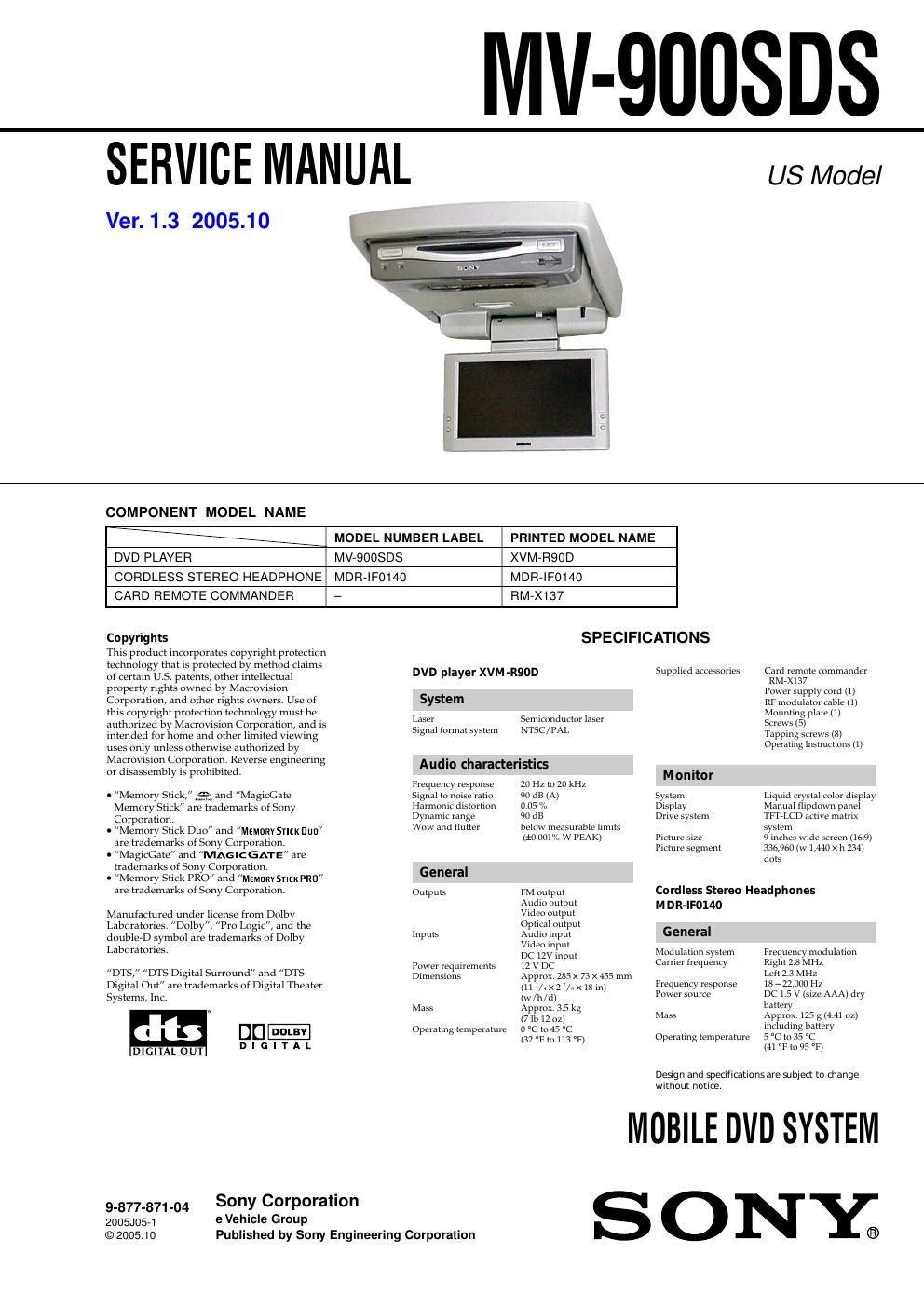
Sony mv 900 sdds service manual

This is the 100 pages manual for sony mv 900 sdds service manual.
Read or download the pdf for free. If you want to contribute, please mail your pdfs to info@audioservicemanuals.com.

Page: 1 / 100
left right
sony mv 900 sdds service manual

Extracted text from sony mv 900 sdds service manual (Ocr-read)


Page 1

NIV-QDUSDS

SERVICE MANUAL

Ver. 1.3 2005.10

US Model

COMPONENT MODEL NAME

MODEL NUMBER LABEL

PRINTED MODEL NAME

DVD PLAYER MV-QOOSDS XVM-RQOD
CORDLESS STEREO HEADPHONE MDR-IFO140 MDR-IF014O
CARD REMOTE COMMANDER - RM-X137

Copyrights

This product incorporates copyright protection
technology that is protected by method claims
of certain US. patents, other intellectual
property rights owned by Macrovision
Corporation, and other rights owners. Use of
this copyright protection technology must be
authorized by Macrovision Corporation, and is
intended for home and other limited viewing
uses only unless otherwise authorized by
Macrovision Corporation. Reverse engineering
or disassembly is prohibited.

. "Memory Stick," nd Magiccate
Memory Stick are trademarks of Sony
Corporation.

0 "Memory Stick Duo" and MEMDRV 51HK Dun
are trademarks of Sony Corporation.

o MagicGate and MAG chATE are
trademarks of Sony Corporation.

0 "Memory Stick PRO and Miriam Snot PRU
are trademarks of Sony Corporation.

Manufactured under license from Dolby
Laboratories. Dolby, "Pro Logic", and the
doublet) symbol are trademarks of Dolby
Laboratories.

"ms," DTS Digital Surround and "ms
Digital Out are trademarks of Digital Theater
Systems, Inc.

«It:

DIGITAL OUT

DIGITAL

9-877-871-04
zoosilosei
© 2005.1 0

e Vehicle Group

DVD player XVM-

System

Laser
Signal format system

SPECIFICATIONS

R90D

Semiconductor laser
\I'l SC / IAL

Audio characteristic:

Frequency response
signal to noise ratio
llarmonic distortion
Dynamic range
Wow and flutter

General
Outputs
lnputs

Power requirements
Dimensions

Vlass

Operating temperature

Sony Corporation

Published by Sony Engineering Corporation

21) [12 to 20 kl 11

91) dB (A)

0.05 %

91) dB

below measurable limits
(totmlta w PEAK)

PM output

Audio output

video output
Optical output
Audio input

Video input

DC lzv input

12 v DC

Approx. 235 x 73 x 453 mm
(ll /ix 27/»x18in)
(w/h/d)

Approx 3.3 kg

(7 lb 12 oz)

0 C to .15 C

(32 01A to 113 31:)

Card remote commander
RM-Xl37

Power supply cord (1)

RF modulator cable (1)

Mounting plate (1)

Screws (5)

lapping screws (H)

Operating lnstriiclions (1)

Supplied accessories

M o nito r
Sysicm L|quld crystal color display
Display .vt nual flipdown panel
Drive system 1 -LCD active matrix

system
9 inches Wide screen (16.9)
336,960 (w 1,440 X I1 234)
dots

Picture size
Picture segment

Cordless Stereo Headphones
M DR-IF014O
General

Vlodiilaiion system
Carrier frequency

Frequency modulation
Right 23 3111;

Left 23 M112

1x r 22,001) 111

DC 1 5 v (size AAA) dry
battery

Approx 125 g (4.41 oz)
including battery

5 c to 35 c

(.11 t to 95 H

rreoiicncy response
Power source

Mass

Operating temperature

Design and specificationsare subject to change
without notice.

MOBILE DVD SYSTEM

S

ONE;

Page 2

MV-QOOSDS

CAUTION

The use of optical instruments with this
product will increase eye hazard.

CAUTION

Use of controls or adjustments or performance of procedures
other than those specified herein may result in hazardous radiation
EXPOSUIC.

Notes on chip component replacement
0 Never reuse a disconnected chip component.
0 Notice that the minus side of a tantalum capacitor may be
damaged by heat.

Flexible Circuit Board Repairing
0 Keep the temperature of the soldering iron around 270 C
during repairing.
0 Do not touch the soldering iron on the same conductor of the
circuit board (within 3 times).
0 Be careful not to apply force on the conductor when soldering
or unsoldering.

Thi 5 located on the drive units internal
Chassis.

3.

3-1.
3-2.
3-3.
3-4.
3-5.

3-7.
3-8r

6-7.
6-8.
6-9

6-10.
6-11.
6-12.
6-13.
6-14.
6-15.
6-16.
6-17.
6-18.
6-19.

7.

7-1.
7-2.
7-3
7-4.
7-5.

8.

TABLE OF CONTENTS


SERVICING NOTES . 3
GENERAL

Location of Controls ........................................................ 5
DISASSEMBLY

Disassembly Flow ........................................................... 9
Bracket (Main) .................... 9
DVD Mechanism Deck Block . 10
MAIN Board ........ 10
Rear Cover (Hinge) 11
LCD Block 11
LCD Board 12
Liquid Crystal D play Panel (LCDl) 12
TEST MODE .............................................................. 13
ELECTRICAL ADJUSTMENTS ......................... l4

DIAGRAMS
Block Diagram 7 MPEG DECODER Section 7
Block Diagram 7AUDIO Section 7
Block Diagram 7 VIDEO, PANEL Section 7
Block Diagram 7 POWER SUPPLY Section
Printed Wiring Board

7 MAIN Board (Component Side) 7 ............................... 24
Printed Wiring Board

7 MAIN Board (Conductor Side) 7 ..........
Schematic Diagram 7 MAIN Board (1/4) 7
Schematic Diagram 7 MAIN Board (2/4) 7
Schematic Diagram 7 MAIN Board (3/4) 7
Schematic Diagram 7 MAIN Board (4/4) 7 ..
Printed Wiring Board 7 LCD Board (Side A) 7
Printed Wiring Board 7 LCD Board (Side B) 7
Schematic Diagram 7 LCD Board (1/4) 7
Schematic Diagram 7 LCD Board (2/4) 7
Schematic Diagram 7 LCD Board (3/4) 7
Schematic Diagram 7 LCD Board (4/4) 7
Printed Wiring Board 7 PANEL Section (1/2) 7 ..
Printed Wiring Boards 7 PANEL Section (2/2)
Schematic Diagram 7 PANEL Section 7.

30


EXPLODED VIEWS

Skirt (Cabinet) Section 54
Front (Panel) Section. 55
MAIN Board Section. 56
Cabinet (Base) Section 57
LCD Section .................................................................... 58
ELECTRICAL PARTS LIST ................................ 59