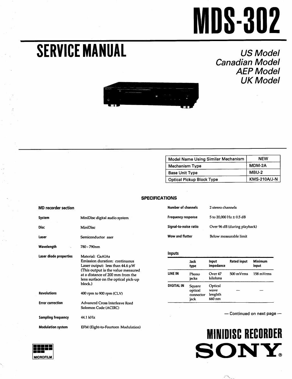
Sony mds 302 service manual

This is the 50 pages manual for sony mds 302 service manual.
Read or download the pdf for free. If you want to contribute, please mail your pdfs to info@audioservicemanuals.com.

Page: 1 / 50
left right
sony mds 302 service manual

Extracted text from sony mds 302 service manual (Ocr-read)


Page 1

mus-302

SERVICE MANUAL

US Model
Canadian Model
AEP Model

UK Model

MD recorder section
System

Disc

Laser

Wavelength

Laser diode properties

Revolutions

Error correction

Sampling frequency

Modulation system

MICROFILM

MiniDisc digital audio system
MiniDisc

Semicondudor asor

780 - 790nm

Material: GaAIAs

Emission duration: continuous
laser output less than 44.6 uW
(This output is the value measured
at a distance of 200 mm from the
lens surface on the optical pick-up
block.)

400 rpm to 900 rpm (CLV)

Advanced Cross Interlmve Reed
Solomon Code (ACIRC)

44.] kHz

EFM (Eight-to-Fourtcon Modulation)

SPECIFICATIONS

Model Name Using Similar Mechanism NEW
Mechanism Type MDM-ZA
Base Unit Type MBU-Z
Optical Pickup Block Type KMS-ZtONJ-N
Number of channels 2 stereo channels
Frequenzy response 5 to 20,000 Hz i 0.5 dB
Signal-tomoise ratio Over 96 dB (during playback)
Wow and flutter Below measurable limit
Inputs
Jack Input Rated input Minimum
type impedanee input
LINE IN Phono Over 47 500 mes 158 mes
jacks kilohms

DIGITAL IN Square Optical

optical wave - _
mnnector lenghth
jack 660 nm

- Continued on next page -

MllllllllSfl ninnnnrn
ONY;

Page 2

Outputs
lack Rated Load
type output impedance
lINE OUT Phone 2 Vrms Over 10 kilohms
jacks (at 50 kilohms)
DIGITAL OUT Square -18 dBm Wave length: 660 nm
optical
connector
pack
PHONES Stereo 28 mW 32 ohms
phone
jack
General
Power requirements

120 V AC, 60 Hz (US, Canadian models)
220 - 230 V AC, 50/60 Hz (AEP model)
220 - 240 V AC, 50/60 Hz (UK model)

Power consumption
19 W (U5, Canadian models)
20 W (AEI, UK models)

Dimensions (approx) (thId)
430 x 97.5 x 292 mm (17 x3 7/3 x 11 '/2 in.) incl.
projecting part5

Mass (approx)
3.5 kg (7 lbs 11 oz)

Supplied accessories
Audio connecting cords (2 phone plugs - 2 phono
plugs) (2)
Remote commander (remote) RM-DSM (1)
Sony SUMvB (NS) batteries (2)

US and foreign patents licensed from Dolby Laboratories
Licensing Corporation.

Design and specifications are subject to change without
notice.

SAFETY-RELATED COMPONENT WARNING

COMPONENTS IDENTIFIED BY MARK A OR DOTTED
LINE WITH MARK A ON THE SCHEMATIC DIAGRAMS
AND IN THE PARTS LIST ARE CRITICAL T0 SAFE
OPERATION. REPLACE THESE COMPONENTS WITH
SONY PARTS WHOSE PART NUMBERS APPEAR AS
SHOWN IN THIS MANUAL OR IN SUPPLEMENTS PUB-
LISHED BY SONY.

ATTENTION AU. COMPQSANT AYANT RAPPORT
A LA SECURITEI

LES composmrs IDENTIFIES PAR UNE MARQUE A
sun LES DIAGRAMMES SCHEMATIQUES at LA LISTE
DES PIECES sour CRITIQUES POUR LA sécunlré
DE FONCTIONNEMENT. NE REMPLACER css com.
posmrs nus PAR DES PIECES SONY oom- LES
numénos som- DONNés DANS c: MANUEL ou
DANS LES SUPPLEMENTS Puaués PAR SONY.

TABLE OF CONTENTS


m Title m;
1_ GENERAL ................................ ........................ 4
2. DISASSEMBLV
2.1_ Case .......t..... ............ ............ 18
2-2. Front Panel -------- 18
2-3. Mechanism Deck '9
2-4 Slider 19
2~5. Base Unit. bonding Motor Assy


2-6. Slider Mounting -'
3. DIAGRAMS
3-1. IC Pin Functions
. 10101 RFAMHCXANSIR) ............................. 21
- 1012] Digital Signal Processor. Digital Servo Signal Processor,
EFM/ACIRC Encoder/Decoder (CXD253SAR) ' 22
- [-‚¬201 System Controller (M37610MD-050FP) ' "25
- lC221 Shock Proof Memory Controller ATRAC Encoder/
Decoder (CXD2536R) .. ------------ 28
34' Circuit Boards Location ............................................ 3
34' pn-med Wiring Boards _ RF Section .. .................... .........32
3-4. Schematic Diagram - RF Section 7
3-5. Schematic Diagram - Digital Section -
3-6. Printed Wiring Boards - Digital Section - 43
3-7. Schematic Diagram - Display/Power Supply Section -
3~8. Printed Wiring Boards - Display/Power Supply Section -
33' Semiconductor Lend Lnyouts .......................................... 55
4. EXPLODED VIEWS
4_1_ Case, antPanel Section ........................... 57
4_2_ Chassis Section ........................................................ 58
44' Mechanism Soction .............. ..............l..l.... .................. 59
44' Base Unit Section ......................................................... 5°
5. ELECTRICAL PARTS LIST .................................. ........61