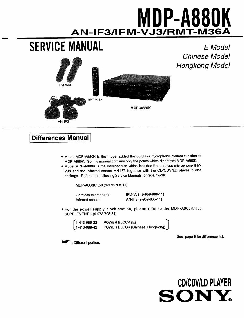
Sony mdp a 880 k service manual

This is the 22 pages manual for sony mdp a 880 k service manual.
Read or download the pdf for free. If you want to contribute, please mail your pdfs to info@audioservicemanuals.com.

Page: 1 / 22
left right
sony mdp a 880 k service manual

Extracted text from sony mdp a 880 k service manual (Ocr-read)


Page 1

MDP-A880K

AN-IF3/IFM-VJ3/RMT-M36A

SERVICE MANUAL E Model

Chinese Model
Hongkong Model

IFM-VJ3

EMT-MESA


V 1m.

M DP-A880 K

Differences Manual

0 Model MDP-ABBOK is the model added the cordless microphone system function to
MDP-A660K. So this manual contains only the points which differ from MDP-A660K.

0 Model MDP-ABBOK is the merchandise which includes the cordless microphone lFM-
VJ3 and the infrared sensor AN-lF3 together with the CD/CDV/LD player in one
package. Refer to the following Service Manuals for repair work.

MDP-A660K/K50 (9973-7084 1 )

Cordless microphone lFM-VJ3 (9-959-868-11)
Infrared sensor AN-IF3 (9-959-865-11)

o For the power supply block section, please refer to the MDP-A660K/K50
SUPPLEMENT-1 (9-973-708-81) .

1-413-989-22 POWER BLOCK (E)
1-413-989-42 POWER BLOCK (Chinese, HongKong)

See page 5 for difference list.

'- : Different portion.

cm ICDVI LD PLAYER
S 0 NY

Page 2

2.

2- I .
2-2.

3.

3-1.
3-2.
3-3.

4- I .
4-2.

TABLE OF CONTENTS

GENERAL

Connecting the Player ........................ 3
Setting up the cordless microphone sysnem ~~~~~~ 3
Preparing the cordless microphoness ---------- 4
DIFFERENCE LIST

EXPLODED VIEWS 5
ELECIRICAL PARTS LIST .................. 6
BLOCK DIAGRAMS

OVERALL BIDCK DIAGRAM ................ 7
KARAOKE BLOCK DIAGRAM ------------- 9
MODE CONTROL BLDCK DIAGRAM ------ 11
PRINTED WIRING BOARDS AND
SCHEMATIC DIAGRAMS

FRAME SCHEMA'I'IC DIAGRAM ------------ 13
PRINTED WIRING BOARD AND SCHEMATIC
DIAGRAM ................................ l 5

SAFETY-RELATED COMPONENT WARNINGII

COMPONENTS IDENTIFIED BY MARK A OR DOTTED
LINE WITH MARK A ON THE SCHEMATIC DIAGRAMS
AND IN THE PARTS LIST ARE CRITICAL TO SAFE
OPERATION. REPLACE THESE COMPONENTS WITH
SONY PARTS WHOSE PART NUMBERS APPEAR AS
SHOWN IN THIS MANUAL OR IN SUPPLEMENTS PUB-
LISHED BY SONY.

. MA-7IlBOARD .............................. 16
. FP-744 BOARD .............................. 19
. TUNER BOARD .............................. 23
5. TUNER BOARD ELECTRICAL
PARTS LIST ......... . ................ 27
6. ELECTRICAL ADJUSTMENT --------- 31

Note for reference page indication in this manual.

See page 4-Cl__|:l 2 Pages on the MDP-AeeoK/K50
5-|:_I|j_ service manual.

See page DE} 2 Pages on this manual.

CAUTION

Use of controls or adiustments performance oi
proeedures other than those specified herein may result
in hazardous radiation exposure.

SAFETY CHECK-OUT

After correcting the original service problem, perform the lollowing
satety checks before releasing the set to the customer.

1. Check the area of your repair for unsoldered or
poorly-soldered connections. Check the entire board
surface for solder splashes and brides.

2. Check the interboard wiring to ensure that no wires
are "pinched" or contact high»wattage resistors,

3. Look for unauthorized replacement parts, par-
ticularly transistors, that were installed during a
previous repair. Point them out to the customer and
recommend their replacement.

4. Look for parts which, throught functioning, show
obvious signs of deterioration. Point them out to the
customer and recommend their replace-ment.

5. Check the B+ voltage to see it is at the values
specified.

6. Flexible Circuit Board Repairing

' Keep the temperature of the soldering iron around
270'C during repairing.

'00 not touch the soldering iron on the same
conductor of the circuit board (within 3 times).

0 Be careful not to apply force on the conductor when
soldering or unsoldering.