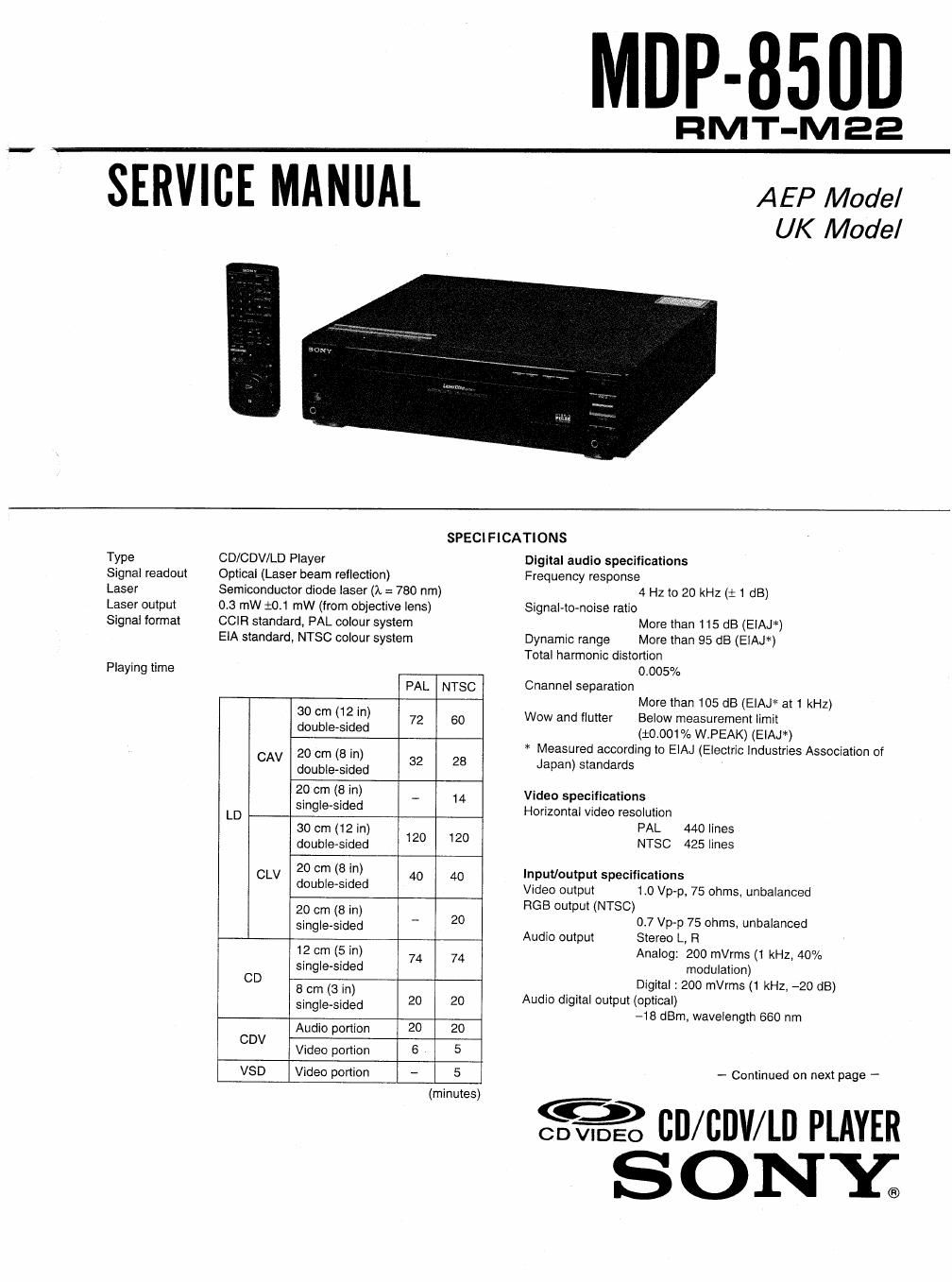
Sony mdp 850 d service manual

This is the 106 pages manual for sony mdp 850 d service manual.
Read or download the pdf for free. If you want to contribute, please mail your pdfs to info@audioservicemanuals.com.

Page: 1 / 106
left right
sony mdp 850 d service manual

Extracted text from sony mdp 850 d service manual (Ocr-read)


Page 1

MOP-8500

RMT-MEE

SERVICE MANUAL

A EP Model
UK Model

Type

Signal readout
Laser

Laser output
Signal format

Playing time

CD/CDV/LD Player

Optical (Laser beam reflection)

SPECIFICATIONS

Semiconductor diode laser (1 = 780 nm)
0.3 mW $04 mW (from objective lens)
CCIR standard, PAL colour system

ElA standard, NTSC colour system

PAL NTSC
30 cm (12 in)
double-sided 72 6°
CAV 20 cm (8 in)
double-sided 32 28
20 cm (a in) _ 14
single-sided
LD 30 ( 2 )
cm 1 in
double-sided 12° 12°
20 cm (8 in)
CLV double-sided 4O 40
20 cm (8 in)
single-sided _ 20
12 cm (5 in)
single-sided 74 74
CD
8 cm (3 in)
single-sided 20 20
Audio portion 20 20
CDV _ .
Video pomon 6 5
VSD Video portion - 5
(minutes)

Digital audio specifications
Frequency response
4 HZ to 20 kHz (i 1 dB)
Signal-to-noise ratio
More than 115 dB (EIAJ*)
Dynamic range More than 95 dB (ElAJ*)
Total harmonic distortion
0.005%
Channel separation
More than 105 dB (ElAJ* at 1 kHz)
Wow and flutter Below measurement limit
(iooom W.PEAK) (EIAJ*)
* Measured according to EIAJ (Electric Industries Association of
Japan) standards

Video specifications

Horizontal video resolution
PAL 440 lines
NTSC 425 lines

Input/output specifications

Video output 1.0 Vp-p, 75 ohms, unbalanced
RGB output (NTSC)
0.7 Vp-p 75 ohms, unbalanced
Audio output Stereo L, R
Analog: 200 mVrms (1 kHz, 40%
modulation)

Digital : 200 mVrms (1 kHz, -20 dB)
Audio digital output (optical)
-18 dBm, wavelength 660 nm

- Continued on next page -

=9nil/cum PLAYER
ONY®

Page 2

Headphone output 28 mW (32 ohms), impedance = 8 ohms
CONTROL 8 IN input
Mini jack
Power requirements
220 - 240 V AC, 50/60 Hz
Power consumption
45 watts
Mass Approx. 9.2 kg
Dimensions Approx. 430 x 115 x 420.5 mm (w/h/d)
Operating temperature
+5°C to +35°C
Ambient humidity 5% to 90%

Remote Commander RMT-Mzz
Remote control system

infrared control
Power requirements
3 V DC, (2 IEC R6 (size AA) batteries)
Approx. 68 x 38 x 200 mm (w/h/d)
Approx. 175 9 (including batteries)

Dimensions
Mass

Supplied accessories

Remote Commander FlMT-M22 (t)

IEC R6 (size AA) batteries (2)
EURO-AV (21-pin) connecting cable (1)
AC power cable (1)

Design and specifications are subject to change without notice.

SAFETY-RELATED COMPONENT WARNINGI!

COMPONENTS IDENTIFIED BY MARK A OR DOTTED
LINE WITH MARK A ON THE SCHEMATIC DIAGRAMS
AND IN THE PARTS LIST ARE CRITICAL TO SAFE
OPERATION. REPLACE THESE COMPONENTS WITH
SONY PARTS WHOSE PART NUMBERS APPEAR AS
SHOWN IN THIS MANUAL OR IN SUPPLEMENTS PUB-
LISHED BY SONV.

To prevent fire or shock hazard, do not expose the unit to rain or
moisture.

To avoid electrical shock, do not open the cabinet. Refer servicing
to qualified personnel only.

Laser component in this product is capable of emitting radiation
exceeding the limit for Class 1.

This CD CDV LD player is
classified as a CLASS 1
LASER product.

The CLASS 1 LASER
PRODUCT label is located on
the rear exterior.

CLASS I LASER PRODUCT
LASER KLASSE 1

LUOKAN 1 LASERLAITE
KLASS 1 LASERAPPARAT

k

CAUTION . INVISIBLE LASER RADIATION WHEN OPEN AND
imatocxs DEFEATED AVOID sxeosuns TQ BEAM

ADVARSEL :usmue msenstnAme vso AeNINc NAR
SIKKERHEDSAFBRYDEHE ER uos AF FUNKTlON. unocA UDSAETTELSE
Foe TRALING

VORSlCHT » UNSICHTBARE LASERSTRAHLUNG. WENN
AEDECKUNG GEOFFNET UND SICHEREITSVEHRIEGELUNG

UBERBHU§5T NicHT DEM §TRAHL A §§§TZEN

VAFtOl .AVATTAESSA u SUOJALUKITUS OHITErrAEssA 04.57 ALTTIINA

NAKYMATTOMALLE LASEHSArEiLv E. ALA KAng §ATEESEEN.

VARNING :oskue LASERSTFIALING MAR DENNA DEL An OPPNAD

OCH §PRHREN fin uanPPLAD. EETRAKTA EJ erA §N

ADVERSEL USYNLIG LASERSTRALING Mn DEKSEL times 05

§I§KERHEDSIJS BRYTES. UNNGA gstONEniNg FOR STRALEN

This label is located on the top cover and inside of the unit.

SAFETY CHECK-OUT

After correcting the original sen/ice problem, perform the following
safety checks before releasing the set to the customer:

1. Check the areas of your repair for unsoldered or
poorly-soldered connections. Check the entire board
surface for solder splashes and bridges.

2. Check the interboard Wiring to ensure that no Wires are
pinched" or contact high-wattage resistors.

3. Look for unauthorized replacement parts, particularly
transistors, that were installed during a previous repair.
Point them out to the customer and recommended their
replacement.

4. Look for parts which. through functioning, show
obvious signs of deterioration. Point them out to the
customer and recommended their replacement.

5.

Check the B+ voltage to see it is at the values

specified.

Flexible Circuit Board Repairing

Keep the temperature of the soldering iron around
270°C during repairing.

- Do not touch the soldering iron on the same
conductor of the circuit board (within 3 times).

- Be Careful not to apply force on the conductor when
soldering or unsolden'ng.