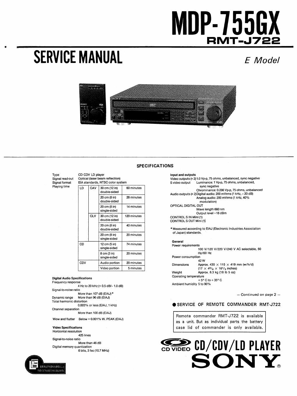
Sony mdp 755 gx service manual

This is the 106 pages manual for sony mdp 755 gx service manual.
Read or download the pdf for free. If you want to contribute, please mail your pdfs to info@audioservicemanuals.com.

Page: 1 / 106
left right
sony mdp 755 gx service manual

Extracted text from sony mdp 755 gx service manual (Ocr-read)


Page 1

MDP-755GX

RMT-J722

ERVICE MANUAL E Model

SPECIFICATIONS
Type CD CDV LD player Input and outputs
Signal madam Optlcal (laser beam reflection) Video outputs (x 201.0 VP-p, 75 ohms. unbalanced, sync negative
signal tonnat ElA Stand-artist NT 50 CDIOV system S video output Lurnlnance: 1 Vop. 75 ohms, unbalanced,
Playing tlme AV 30 12 - 60 - sync negative
LD 0 dost)? e(-sl (1'2; mmmes chrominanoe: 0.286 Vp-p, 75 ohms, unbalanced
. Audio outputs (X ZlDlgital audio: 200 mVrms (1 kHz, - 20 dB)
20 Cm (3 In) 23 minutes Analog audio: 200 mVrms 11 kHz. 40%
doublesided modulation)
20 cm (3 in, 14 minutes OPTICAL DIGITAL our
singlesided Wave length 660 nm
, . Output level -18dBm
CLV 30 cm (12: in) 120 minutes CONTROLS IN Mlnl l1) .
Wmfi'dw CONTROL 5 OUT Mini (1)
20 cm (8 in) 40 minutes
double-sided Measured according to ElAJ (Electronic Industries Association
20 cm (a in) 20 minutes at Japan) standards.
slngIe-sided G I
y enera
CD 1? cm (5- ml 74 minutes Power requirements
S'"9'95'd°d 100 mm w220 VI240 V AC seiembie. so
8 cm (3 in) 20 minutes Hz/so Hz
singlesided Power consumption
. . . 42 W
CDV Ad'° p°'°" 2° ""mes Dimensions Appm 430 x 15 x 419 mm (w/h/d)
Video portion 5 minutes (17 X 45/l X 16]; inches)
Weight Approx are kg (18 II: 5 oz)
. . . . Operating temperature
Digital Audio Specifications + 5° C 3+ 35° 0

Frequency response

4 Hz to 20 kHz l+ 0.5 dB/- 1.0 dB}
Signal-tonoise ratio

More than 107 dB (ElAJ)
Dynamic range More than 96 dB (ElAJ)
Total harmonic distortion

0.003% or leslelAJ. 1 kHz) 0 SERVICE OF REMOTE COMMANDER RMT-J722
Channel separation

More than 100 dB (ElAJJ

Wow and flutter Below + 0.001 "/a w. PEAK (EIAJ)

Ambient humidity 5 to 90%

- Continued on page 2 -

Remote commander RMT-J722 is available
as a unit. But as individual parts the battery

VideoSpeciliCItions case lid of commander is only available.

Horizontal resolution
425lines

Signal-tonoise ratio

em (0% CD / CDV/LB PLAYER

SONY;

Page 2

Re te Com der R
Prlnclple oi operation
Infrared pulse

Power requirements

Dimensions

Welght

3 V Dc (Two size H6 batteries)

Approx. 105 x 43 X157 mm (wlhldl

(41/4 X 1]. X 6% inches)

Approx. 260 g (9 oz) including batteries

Accesso s Supplied

Remote Commander FtMTJ722 (1)

Size R6 batteries (2)

Video connecting cable (1 phone to 1 phono) (1)
Audio connecting cable (2 phone to 2 phone) (1)
AC plug adaptor (1)

Design and specifications are subject to change without notice.

SAFETY CH EC K-OUT

After correcting the original service problem, perform the following
safety checks before releasing the set to the customer:

Check the area of your repair for unsoldered or
poorly-soldered connections Check the entire
board surface {or solder splashes and bridges.

Check the interboard wiring to ensure that no
wires are "pinched" or contact high-wattage
resistors.

Look for unauthorized replacement parts. par-
ticularly transistors, that were installed during a
previous repair. Point them out to the customer
and recommend their replacement.

Look for parts which,though functioning, show
obvious signs of deterioration. Point them out
to the customer and recommend their replace-
ment.

Check the line cord for cracks and abrasion.
Recommend the replacement of any such line
cord to the customer.

Check the B+ voltage to see it is at the values
specified.

Check the antenna terminals, metal trim,
metallized knobs, screws, and all other
exposed metal parts for AC leakage. Check

leakage as described below.

LEAKAGE TEST

The AC leakage from any exposed rnctal purl to

earth ground and from all expOsed metal parts to any
exposed metal part having a return to chassis, must

not exceed 0.5 mA (500 microampers).

Leakage

cmrent can be measured by any one of three
methods,

A commercial leakage tester, such as the
Simpson 229 or RCA WT-S40A. Follow the
manufacturers' instructions to use these instru-
ments.

It battery-operated AC milliammeter. The Data
Precision 245 digital multimeter is suitable for
this job.

Measuring the voltage drop across a resistor by
means of a VOM or batteryvoperated AC volt-
meter. The limit" indication is 0.7SV, so
analog meters must have an accurate low-
voltage scale. The Simpson 250 and Sanwa
SH'63Trd are examples of a passive VOM that
is suitable. Nearly all battery operated digital
multimeters that have 3 2V AC range are
suitable. (See Fig. A)

To Exposed Metal
Part: on Set

AC
0.15uF gum / voltmeter
(0.7

5V}
'___I

'2': Earth Ground

Fig, A. Using an AC voltmeter to check AC leakage.

CAUTION

Use of controls or adjustments or performance of
procedures other than those specified herein mav
result in hazardous radiation exposure.

As the laser beam used in this Videodisc Plaver
is harmful to eyes. do not attempt to disassemble
the cabinet.

Refer servicing to qualified personnel only,

SAFETY-RELATED COMPONENT WARNINGII
COMPONENTS IDENTIFIED BY MARK A OR DOTTED

LINE WITH MARK A

ON THE SCHEMATIC DIAGRAMS

AND IN THE PARTS LIST ARE CRITICAL T0 SAFE

OPERATION.

REPLACE THESE COMPONENTS WITH

SONY PARTS WHOSE PART NUMBERS APPEAR AS
SHOWN IN THIS MANUAL OR IN SUPPLEMENTS PUB-

LISHED BY SONY.

_2__