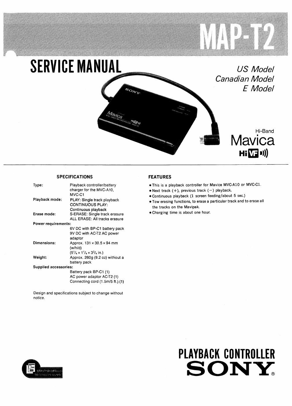
Sony map t 2 service manual

This is the 42 pages manual for sony map t 2 service manual.
Read or download the pdf for free. If you want to contribute, please mail your pdfs to info@audioservicemanuals.com.

Page: 1 / 42
left right
sony map t 2 service manual

Extracted text from sony map t 2 service manual (Ocr-read)


Page 2

MAP-T2

Precautions

- Use the camera and the playback controller as tar from the TV set
as possible.

When placed on the TV set, the picture played back may be poor.
or the picture recorded may not show.

- The MAP-[2 IS a playback controller lor the MVC-A10 or MVC based on the ME»! or ME tormat. Mavipak recorded by an
electronic still camera that does not have the Run or urn-t)
format may not play back correctly.

- Operate the unit only with the supplied battery pack or the AC
power adaptor

. Do not leave the unit in a location near heat sources, or in a place
subject to direct sunlight. excessive dust, or mechanical shock.

0 When the casing becomes soiled, clean it with a soft cloth
dampened with mild detergent solution. Never use abrasive
cleansers or chemical solvents, as they may harm the casing.

Notes on chip component replacement

0 Never reuse a disconnected chip component

0 Notice that the minus side of a tantalum capaci
damaged by heat.

SAFETY-RELATED COMPONENT WARNINGII

COMPONENTS IDENTIFIED BY MARK A OR DOTTED
LINE WITH MARK A ON THE SCHEMATIC DIAGRAMS
AND IN THE PARTS LIST ARE CRITICAL TO SAFE
OPERATION. REPLACE THESE COMPONENTS WITH
SONY PARTS WHOSE PART NUMBERS APPEAR AS
SHOWN IN THIS MANUAL OR IN SUPPLEMENTS PUB«
LISHED BY SONY.

ATTENTION AU corvIPQSANT AYANT RAPPORT
A LA SECURITE!

LES COMPOSANTS IoENTiErEs PAR UNE MAROUE A
sUR LES DIAGRAMMES scr-tEMATmUEs ET LA LISTE
DES PrEcEs SONT CRITIQUES POUR LA SECURITE
DE FONCTIONNEMENT. NE REMPLACER CES COM-
POSANTS QUE PAR DES PIECES SONY DONT LEs
NUMERos SONT ooNNEs DANS CE MANUEL ou
oANs LES SUPPLEMENTS PUBLIES PAR sonv.

TABLE OF CONTENTS
Seclion :zflg fig

1. SERVICING NOTE

1-1. Test Mode ...................................... 3
1-2. Cautions for Measurement of Voltages and
Waveforms ...................................... 4
2. GENERAL
2-1. Quick Reference .................................. 5
2-2. Location and Function of Parts .................. 5
2-3. Power Source .................................... 6
2-4. Connecting to a TV Set .......................... 7
2-5. Playback on a TV Screen ........................ 8
2-6. To Erase Unnecessary Track (S) .................. 9
27. To Re-record Sound Independently .............. 10

3. DISASSEMBLY

3-1. Cobinet (Upper) ................................ 11

3-2 Bottom Plate .................................... 11
4. DIAGRAMS

4-1. Video Block Diagram ............................ 12

42. System Contror/Power Supply Block Diagram 15

4-3. IC Block Diagram .............................. 17

4-4 Printed Wiring Board wVideo(1),System
Control/ Power Supply Section ~(Former Type) r .19
4-5. Printed Wiring Board -Video(1),System

Control/Power Supply Section -(New Type) . . a .23
4-6, Schematic Diagram -Video(1), System

Control/Power Supply Section - ................ 27
4-7. Schematic Diagram -Video(2), Section - ........ 31
4-8. Printed Wiring Board -Video(Z), Section - ...... 35

5. EXPLODED VIEW
5-]. Main Section ................................... 39

6. ELECTRICAL PARTS LIST ...................... 40