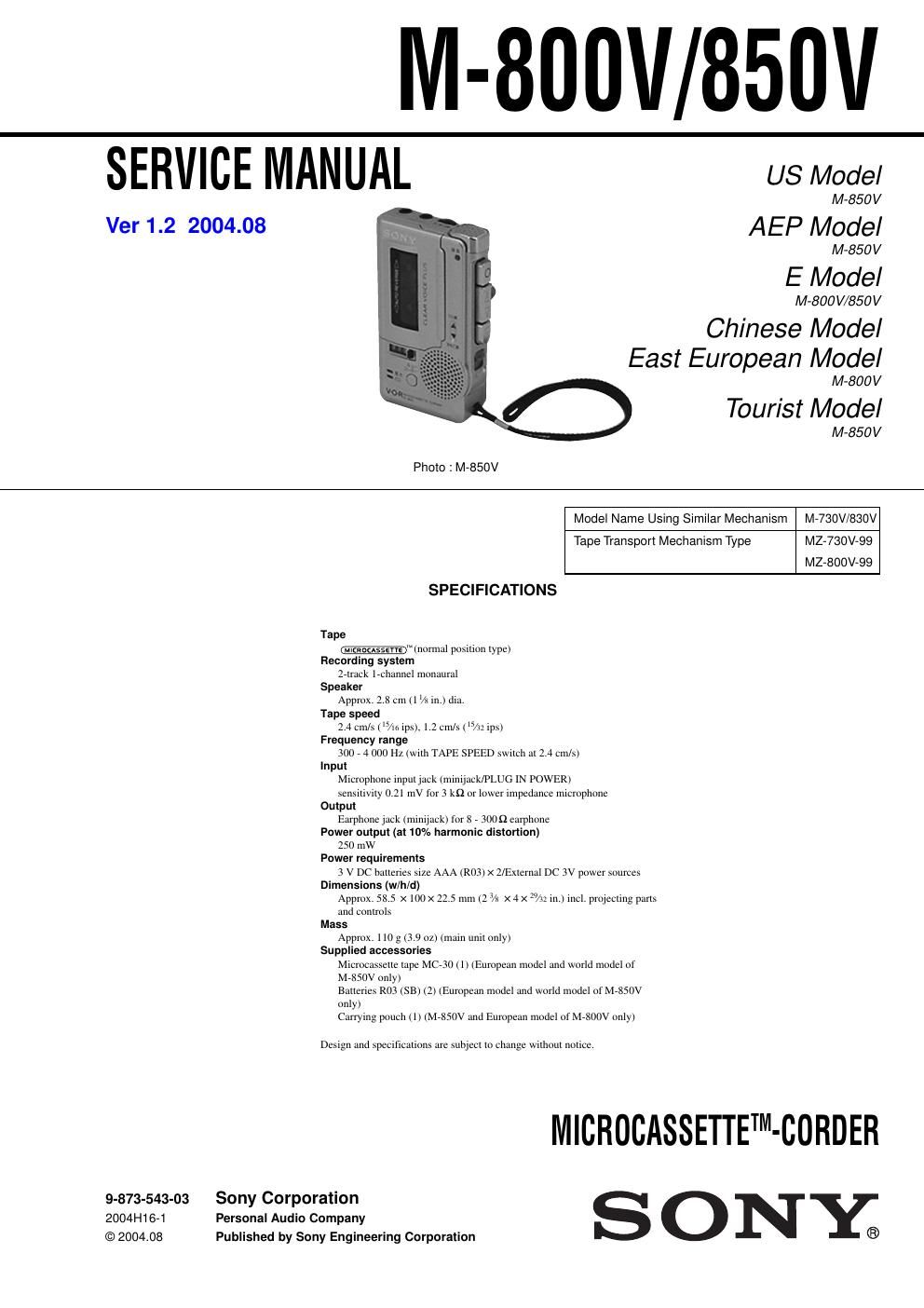
Sony m 850 v service manual

This is the 22 pages manual for sony m 850 v service manual.
Read or download the pdf for free. If you want to contribute, please mail your pdfs to info@audioservicemanuals.com.

Page: 1 / 22
left right
sony m 850 v service manual

Extracted text from sony m 850 v service manual (Ocr-read)


Page 1

2 M-800V/850V TABLE OF CONTENTS Notes on Chip Component Replacement -Never reuse a disconnected chip component. -Notice that the minus side of a tantalum capacitor may be dam- aged by heat. Flexible Circuit Board Repairing -Keep the temperature of the soldering iron around 270˚C during repairing. -Do not touch the soldering iron on the same conductor of the circuit board (within 3 times). -Be careful not to apply force on the conductor when soldering or unsoldering. 1. GENERAL.................................................................... 3 2. DISASSEMBLY 2-1. Cassette Lid Assy ···························································· 4 2-2. Cabinet (Rear) Sub Assy, Lid, Battery Case ··················· 5 2-3. MAIN Board Section ······················································ 5 2-4. LED Board, Battery Holder ············································ 6 2-5. Mechanism Deck (MZ-730V-99)(MZ-800V-99) ············ 6 2-6. Speaker (2.8cm) (SP901) ················································ 7 2-7. Microphone (MIC901) ···················································· 7 2-8. Ceramic Head (HRPE901,902) and DC Motor (M901) ···················································· 8 3. MECHANICAL ADJUSTMENTS.............................. 9 4. ELECTRICAL ADJUSTMENTS............................... 9 5. DIAGRAMS 5-1. Block Diagram .............................................................. 11 5-2. Printed Wiring Board .................................................... 12 5-3. Schematic Diagram ....................................................... 13 5-4. Block Diagram .............................................................. 14 6. EXPLODED VIEWS 6-1. Cabinet Section ............................................................. 15 6-2. Mechanism Deck Section (1) (MZ-730V-99)(MZ-800V-99) ....................................... 16 6-3. Mechanism Deck Section (2) (MZ-730V-99) .............................................................. 17 6-4. Mechanism Deck Section (2) (MZ-800V-99) .............................................................. 18 7. ELECTRICAL PARTS LIST..................................... 19 SERVICING NOTE [How to recognize MZ-730V-99 and MZ-800V-99] MZ-730V-99 DC motor (M901) MZ-800V-99 DC motor (M901) Ver 1.1 2004.01