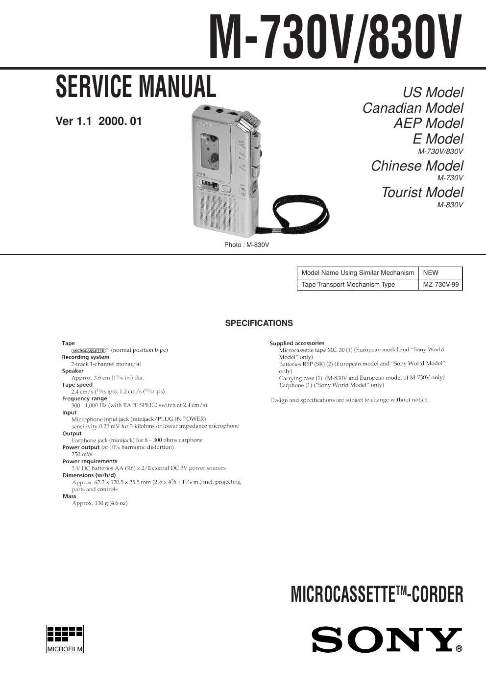
Sony m 730 v service manual

This is the 20 pages manual for sony m 730 v service manual.
Read or download the pdf for free. If you want to contribute, please mail your pdfs to info@audioservicemanuals.com.

Page: 1 / 20
left right
sony m 730 v service manual

Extracted text from sony m 730 v service manual (Ocr-read)


Page 1

Ð 2 Ð TABLE OF CONTENTS Flexible Circuit Board Repairing ·Keep the temperature of the soldering iron around 270ûC during repairing. ·Do not touch the soldering iron on the same conductor of the circuit board (within 3 times). ·Be careful not to apply force on the conductor when soldering or unsoldering. Notes on Chip Component Replacement ·Never reuse a disconnected chip component. ·Notice that the minus side of a tantalum capacitor may be dam- aged by heat. 1. GENERAL.................................................................... 3 2. DISASSEMBLY 2-1. Lid Assy, Cassette ............................................................... 4 2-2. Lid, Battery Case ................................................................ 4 2-3. Cabinet (Rear) Assy ............................................................ 5 2-4. Speaker Assy, Microphone .................................................. 5 2-5. Main Board ......................................................................... 6 2-6. Mechanism Deck ................................................................. 6 2-7. LED Unit ............................................................................. 7 2-8. Head, Creamic (HRPE901, 902) ......................................... 7 3. MECHANICAL ADJUSTMENTS.............................. 8 4. ELECTRICAL ADJUSTMENTS............................... 8 5. DIAGRAMS 5-1. Block Diagram .................................................................. 11 5-2. Printed Wiring Board ........................................................ 13 5-3. Schematic Diagram ........................................................... 15 6. EXPLODED VIEWS 6-1. Cabinet Section ................................................................. 17 6-2. Mechanism Deck Section (1) ............................................ 19 6-3. Mechanism Deck Section (2) ............................................ 20 7. ELECTRICAL PARTS LIST..................................... 21

Page 2

Ð 3 Ð SECTION 1 GENERAL 1 VOL knob 2 MIC jack 3 EAR jack 4 VOR switch 5 REC/BATT lamp 6 FAST PB switch (M-830V ONLY) 7 DC IN 3V jack 8 TAPE COUNTER 9 CUE MARKER button (M-830V ONLY) 0 i(Battery) lamp (M-830V ONLY) !Á Microphone !ª r(REC) button !£ C PAUSE knob !¢ Ï(Playback) button !° CUE/REVIEW knob !¤ TAPE SPEED select knob !¦ wp(Eject/Stop) button !¥ DIR c knob !» FWD/REV ·