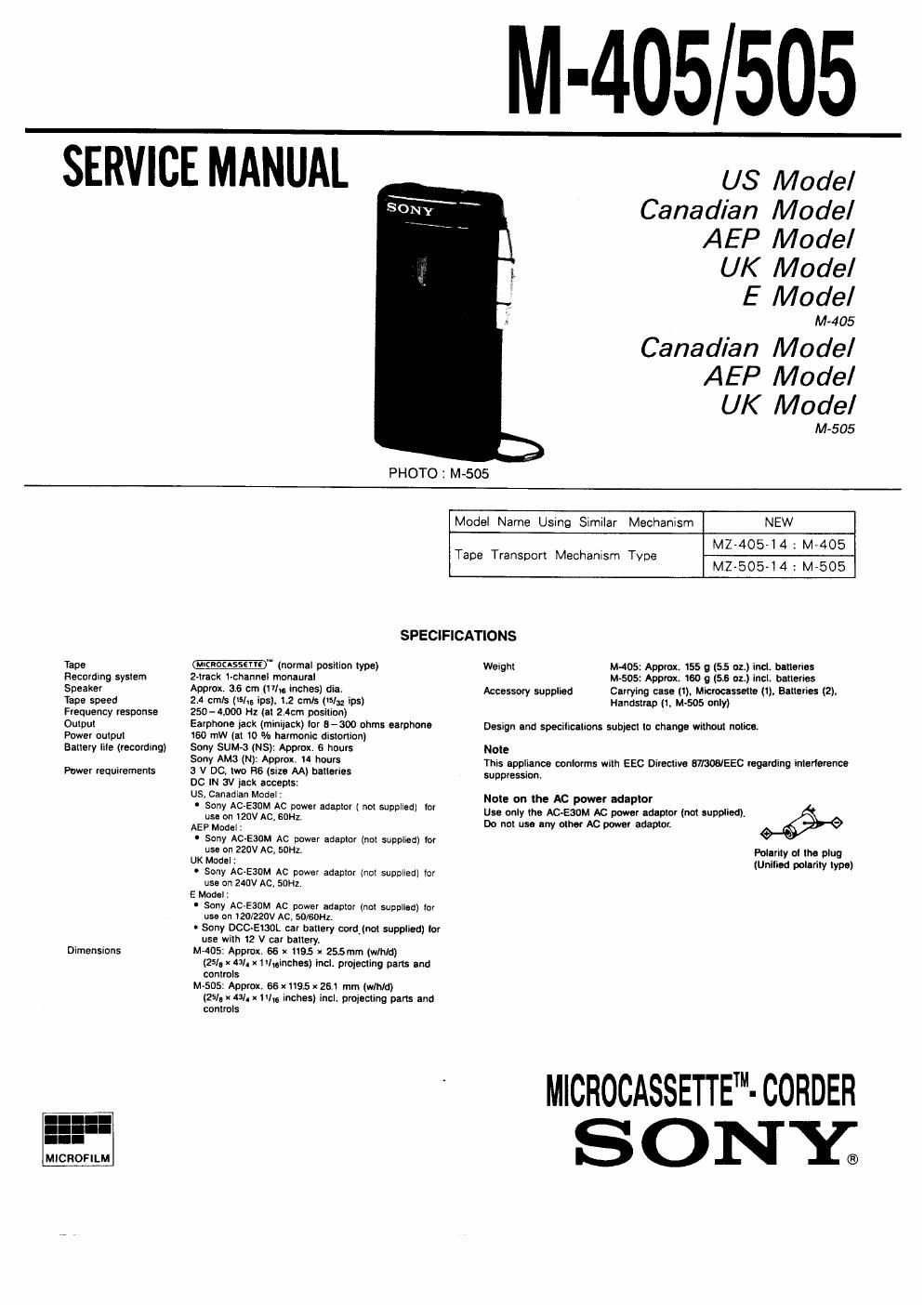
Sony m 505 service manual

This is the 7 pages manual for sony m 505 service manual.
Read or download the pdf for free. If you want to contribute, please mail your pdfs to info@audioservicemanuals.com.

Page: 1 / 7
left right
sony m 505 service manual

Extracted text from sony m 505 service manual (Ocr-read)


Page 1

SERVICE MANUAL

M-405 505

US Model
Canadian Model
AEP Model

UK Model

E Model

M~405

Canadian Model
AEP Model

UK Model

M605

PHOTO : M-505

Model Name Using Similar Mechanism NEW

MZ»405-l4 : M4105
MZ-505-14:M-505

Tape Transport Mechanism Type

SPECIFICATIONS
Tape -' (normal position type) Weight M405: Approx. 155 g (55 oz.) incl. batteries
Recording system 2-track 1-channel monaural M-505: Approx. 160 g (5.6 oz.) incl. batteries
Speaker Approx. 3-6 cm (1 "In inchBS) dla. Accessory supplied Carrying case (i). Microcassette (I), Batteries (2).
Tape speed 2.4 ml: (he ins}, 1-2 cm/s (/32 m) Handstrap (r, M~505 only)
Frequency response 250-4900 Hz (at 2.40m positron)
Output Earphone I35k (Villa) '0' 5-300 0""5 earphone Design and specifications subject to change without notice.

Power output
Battery llIe (recording)

160 mW (at 10 In harmonic distortion)
Sony SUM-a (NS): Approx. 6 hours
Sony AM: (N): Approx. to hours
3 V DC, two He (size AA) batteries
DC lN av jack accepts:
US, Canadian Model:
' Sony AC use on 120v Ac, squ.
AEP Model :
' Sony Ac-EaaM Ac power adaptor (not supplied) ror
use on 220V AC, SDHZ.
UK Mode| :
- Sony AOEBDM Ac power adaptor (not supplied) tor
use on 240v Ac. son,
E Model:
0 Sony AC~E30M Ac power adaptor (not supplied) tor
use an taolzzov Ac, solsot-lz.
U Sony DCC-EISOL car battery cardinal supplied) tor
use with t2 V car battery.
M405: Apprutt. 66 x 1195 x 25.5 mm (wlhld)
(25/. x 43/. X1il..inches) incl, projecting parts and
controls
M-505: Approx. 66 X1195 x 261 mm (w/hld)
(25/. x 43/) x 111; inches) incl, projecting pans and
controls

Power requirements

Dimensions

Note
This appliance contorms with EEC Directive limos/EEC regarding intoflsrence

suppression.

Polarity at the plug
(Unified polarity type)

Note on the AC power adaptor
Use only the ACAESDM AC power naeptor (not supplied),
Do not use my other AC power adaptor.

MICROCASSETTE"- CORDER

SONE

Page 2

ii -L>Ub/5Ob

PARTS IDENTIFICATION

This section is extracted from
instruction manual.

El EAR (earphone) lack
El (7 VOL (volume) control
E] Cassette holder

El TAPE COUNTER and counter
reset button
(M-SOS only)

TAPE SPEED (2.4cm/1.2cm)

E BATT (battery) indicator
(M-SOS only)

El muss switch
E] . (recordlng) button

« CUE-last lomaru/
» REVIEW-rewlnd control

IE <(playbeok) button

MAINTENANCE

Cleaning the heads

Clean the tape heads alter every 10 hours ol use Io enjoy optimum
sound. Moislen a cotton swab or is soft cloth wilh alcohol and wipe the
pans shown in the illustration.

Recordlplayback head

Cepslan Erase head

Pinch-roller

Cleaning the casing

Clean the casing with a soil cloth slightly moistened with water or a
mild detergent solution. on not use alcohol. benzine or lhinner as they
may mar the finish.

Notes on Microcassette

To rouse I cassette
Cover the slot with plastic taper

To protect cassettes lrorn
accidental ensure

Break Gui and
remove the tab,

Plasiic tape

71" @ll

@I/I
i=6?

This unit uses only standard Microcassenes. Non standard
casseiles cannot be used because their L" dimension (see
illustration) is diflerenlt

Only standard


Standard Microcassenes have Non slandlrd
-.___ a small indentation
~-~\_0r- on side A.
- rox. Approxi ,
®"I@ Mm 2.5 mm ©ll©
L 1-
L raw

witch (left side) musket/MOP) bum"

9'99 C 'N V (memfi' FAST PB (last playback)
power Input) lack (left side) switch

Speak-r (built-in) Handstrap catch

IE am. compartment (rear) Handslrap (supplied with
Mic (built-in microphone) M-505 only)

SERVICING NOTE

Repairing printed resistor

Cut both sides of the resistor and solder the carbon resistor
having same value in place of primed one of the conductor
side.

l/4W carbon resistor is supplied for the replacing part of
the printed resistor.

Notes on chip component replacamant
- Never reuse a disconnected chip component.

- Notice that the minus side of a tantalum capacitor may be
damaged by heat.