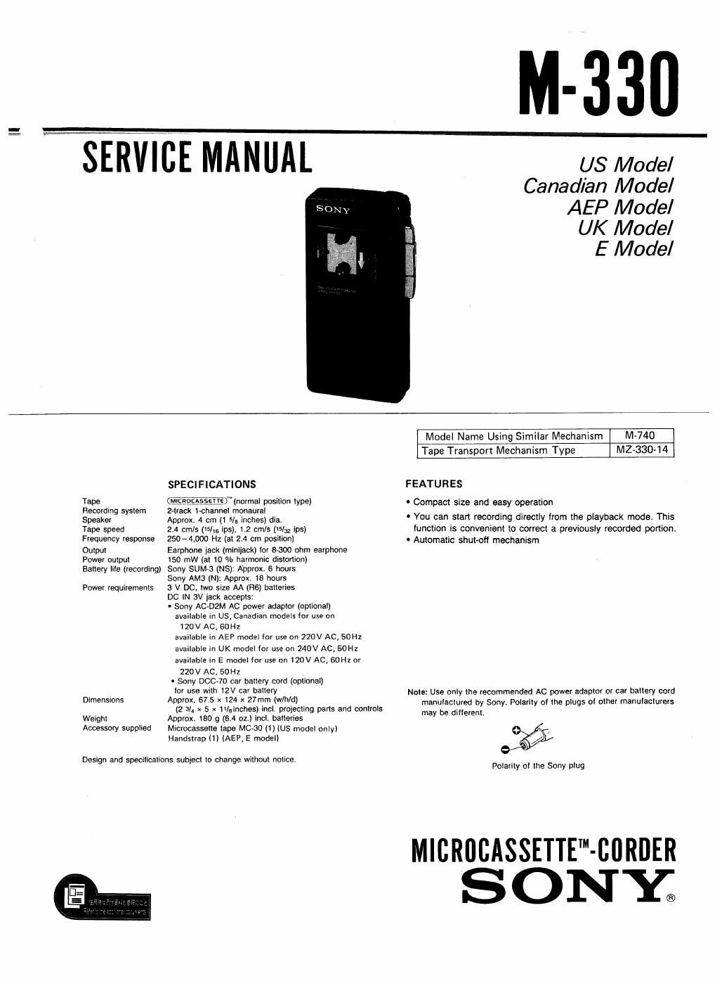
Sony m 330 service manual

This is the 13 pages manual for sony m 330 service manual.
Read or download the pdf for free. If you want to contribute, please mail your pdfs to info@audioservicemanuals.com.

Page: 1 / 13
left right
sony m 330 service manual

Extracted text from sony m 330 service manual (Ocr-read)


Page 1

EEWIBE MANUAL

US Model
Canadian Model
AEP Model

UK Model

E Model

SPECIFICATIONS

Tape W)Winorrnal position type)
Recording system 2-track 1£hannel monaural

Speaker Approx. 4 cm (1 5/5 inches) dia.

Tape speed 24 cmls (VS/is ips). t2 cmls 05/32 ips)
Frequency response 250-4900 Hz (at 2.4 cm position)

Output Earphone jack (miniiack) tor 8:500 ohm earphone
Power output 150 mW (at to % harmonic distortion)

Battery lile (recording) Sony SUM-3 (NS): Approx. 6 hours
Sony AMG (N): Approx. 18 hours
Power requirements 3 V DC, two size AA 1H6) batteries
DC lN 3V jack accepts:
- Sony ACDZM AC power adaptor (optional)
available in US, Canadian models lor use on
120V AC, SOHZ
available in AEP model for use on 220V AC, 50Hz
available in UK model for use on 240V AC, SOHI
available in E model for use on 120V AC, SOHZ or
220V AC, 50Hz
' Sony DOC-70 car battery cord (optional)
tor use with 12V car battery

Dimensions Approx, 67.5 x 124 x 27mm (wlhld)
(2 3/4 x 5 x /gll'lches) incl. projecting pans and controls
Weight Approx. 180 g (6.4 oz.) incl. batteries

Accessory supplied Microcasselte tape MC<30 (1) (Us model only)
Handstrap (1) (AEP, E model)

Design and specifications subiect to change without notice.

Model Name Using Similar Mechanism M-740
Tape Transport Mechanism Type MZ-330-14

FEATURES

e Compact size and easy operation

0 You can start recording directly from the playback mode. This
lunction is convenient to correct a previously recorded portion.
- Automatic shut-oft mechanism

Note: Use only the recommended AC power adaptor or car battery cord
manulactured by Sony Polarity ol the plugs ol other manulactuiers

may be dillerent.

Polarity ol the Sony plug

MlCRllliASSETIE-CBRDER
ONY;

Page 2

M-330

LOCATION OF CONTROLS

EAFt (earphone) lack

Cassette holder

TAPE SPEED selector (left side)
DO IN 3 V (external power input) lack (leit side)-.

Speaker

Battery compartment (rear)

NOTES ON MICROCASSETTE

To reuse a cassette
Cover the slot with plastic
taper

To protect cassettes irom
accidental erasure

Break out and
remove the tabt

Elastic tape

\

<13!

( This unit uses only standard Microcassettes. Non
standard cassettes cannot be used because their "L"
dimension (see illustration) is diiierenll

Only standard
Standard Microcassetles have Non standard
._ ., a small indentation n
-er-' on side A. u

Approx, Approx.

5mm 2.5 mm

4 L
met Lrifig

k

MAINTENANCE

Record/playback head

Erase
head

Cleaning the head

Capslan

VOL (volume) control
Built-In microphone
PAUSE switch

0 (record) button
CUE« (last torward)/REVIEW» (rewind) control

V (playback) button

I l e (stop/eject) button

Handstrap catch

SERVICING NOTE

Repairing printed resistor

Cut both sides of the resistor and solder the carbon resistor
having same value in place of printed one of the conductor
side.

1/ 4W carbon resistor is supplied for the replacing part of the
printed resistor.

Notes on chip component replacement

0 Never reuse a disconnectedchip component.
0 Notice that the minus side of a tantalum capacitor
may be damaged by heat.

Clean the tape head alter every 10 hours oi

use to enjoy optimum sound. Moisten a
cotton swab or a soil cloth with alcohol
and wipe the parts shown in the illustra-
lions

Pinch roller

Cleaning the casing

Clean the casing with a soil cloth slightly moistened with water
or a mild detergent solutions Do not use alcohol, benzlne or
thinner as they may mar the iinish.